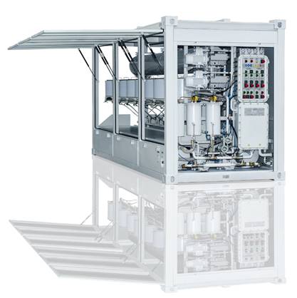
Transformer oil regeneration plant UVR (with special adsorbent, capacity 100 – 300 LPH)
Transformer oil regeneration plant UVR (with special adsorbent, capacity 100 – 300 LPH)
APPLICATION OF MINERAL OIL REGENERATION PLANT
The mineral oil regeneration plant type UVR-0.1 is intended for purification from solid mechanical contaminants as well
as for regeneration/reclamation and decolorization of the
following mineral oil types:
- Insulating Oil
- Turbine Oil
- Lubricating and Hydraulic Oil
- Industrial oil
- Motor oil
- Compressor Seal Oil
- Diesel oil
- Cutting and Cooling Mineral Oil
- Furnace oil
The viscosityof the recoveredproductat 500C shall not exceed70sSt, moisture contentshall not exceeding200 g/ t
Industrial, insulating, turbine andmotor oilsare suitableto regenerate afterfirst removing thefuel, water, hydroxy acids, carbenesand asphaltenes.
FEATURES:
- easy to install and operate. No special training
required; - the plant is completed with set of spare partssufficient for 2 years operating;
- equipped with digital temperature controller
Operational conditions:
Ambient temperature in range from +5ºC to +50ºC;
Atmospheric pressure from 84 to 106.7 kPa (630 to 830
mm. hg.);
Height above mean sea level up to 2000 m.
TECHNICAL SPECIFICATION
|
№ |
Parameter |
Value |
|
| UVR-0.1 | UVR-0.2 | ||
| 1 | Capacity, L/h:diesel fuel oil
turbine oil transformer oil pyrolyze oil furnace |
80-100
80-100 80-100 80-100 80-100 |
160-200
160-200 160-200 160-200 160-200 |
| 2 | Adsorbent consumption by regeneration of, %:diesel fuel oilturbine oil transformer oil pyrolyze oil furnace |
3-10
5-7 5-7 3-10 7-10 |
3-10
5-7 5-7 3-10 7-10 |
| 3 | Weight of adsorbent powder, kg:in one cartridgein all cartridges |
8-10
80-100 |
8-10
160-120 |
| 4 | Loss of oil after regeneration from initial processedoil volume, %:diesel fuel oil turbine oil transformer oil pyrolyze oil furnace |
1-3 3-5 3-5 1-3 1-5 |
1-3 3-5 3-5 1-3 1-5 |
| 5 | Installed capacity, kW | 7-10 | 7-10 |
| 6 | Heating capacity, kW |
3,3 | 6,6 |
| 7 | Power supply, 3 Ph, ~V, 50 Hz |
380 | 380 |
| 8 | Filtration fineness, µminput filter
output |
25
5 |
25
5 |
| 9 | Dimensions, mm | 2650x1400x2100 | 2650x1400x21002400x1300x2100 |
| 10 | Weight, not more, kg | 1300 |
2160 |
DESIGN & OPERATION PRINCIPLE
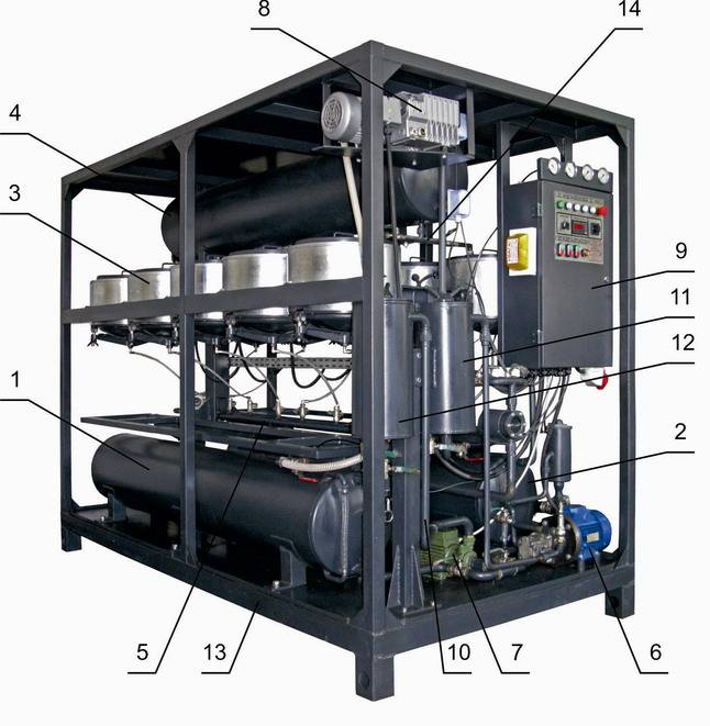
Figure 1. General view of the plant
The oil regeneration plant consists of: 1. Lower tank 1; 2. Lower tank 2; 3. Regeneration module; 4. Upper tank; 5. Comb; 6. Inlet pump; 7. Outlet pump; 8. Vacuum pump; 9. Control panel; 10. Piping; 11. Input filter; 12. Output filter; 13. Base metal frame; 14. Feeding piping.
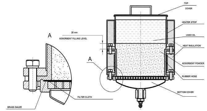 |
Figure 2. Regeneration moduleRegeneration unit”DB” is the tank to half-filled with regenerating powder which provides the proper oil regeneration process. Filling in of regenerating powder and oil feeding is possible from the top of the module. The lower part of the module consists of the shell filled with the regenerating powder, and the bottom cover, providing the unit evacuation, recovered oil extraction and waste powder pour out. The outer surface of the regeneration module is taped by electric heater and insulated with heat insulator. |
| INDUSTRIAL OIL AFTER REGENERATION | |
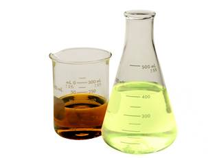 |
TRANSFORMER OIL AFTER REGENERATION |
| FURNACE OIL AFTER REGENERATION | 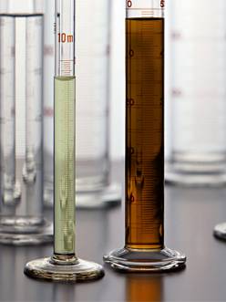 |