Transformer oil purification system CMM-2.2 (capacity 2200 LPH)
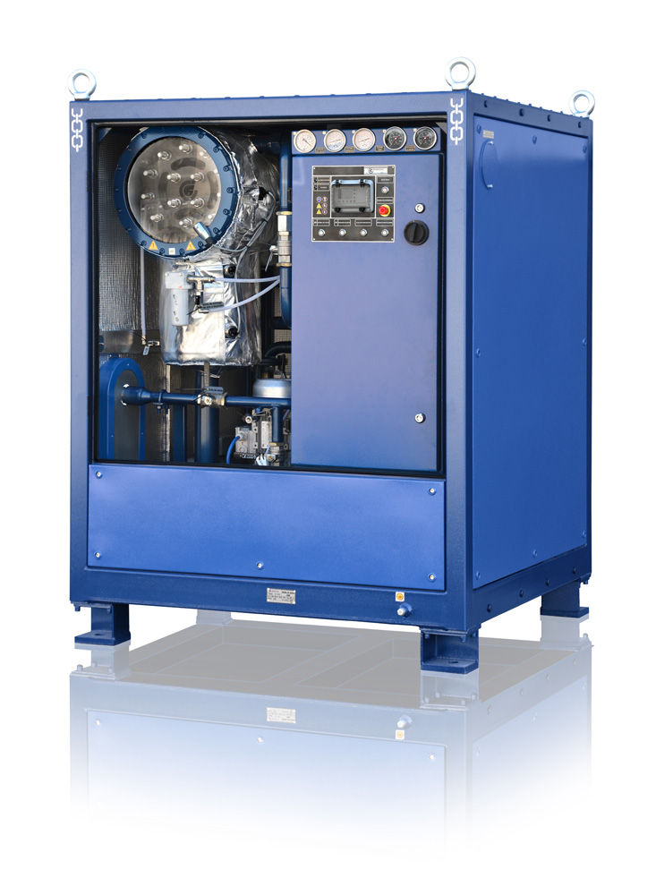
CMM-2.2 General view
(Trailer as option)
GENERAL INFORMATION
Transformer Oil Purification Plant modelСММ-2.2 purifies insulating oils of mechanical particles and employs thermal vacuum for water and gas removal. Operate the Unit when assembling, servicing and exploiting oil filled equipment. Moisture, solids and gaseous contaminants can seriously affect the function of insulating fluids as a coolant and insulator. Unit is used for installation, repair and
maintenance companies which are dealing with transformer oil treatment.
This specification describes the equipment as supplied by GlobeCore for the processing (degasification, dehydration, filtration) of oil. The purifiers are designed for processing of oil in workshops or in the field, in storage tanks, drums. For purification of oil in the field, a mobile type purification plant, mounted on a roadworthy trailer is recommended.
The scope of supply of this specification shall include the design, fabrication and factory testing of Oil Purification Plant CMM-2.2. Equipment will be mounted on a common base or in a trailer and supplied in the form of a pre-piped and pre-wired package and shall provide a fully workable unit in accordance with this specification when received by the purchaser.
Performance in a single pass through the purifier at a full flow rate shall be as follows:
Water Removal: From 50 ppm down to less than 10 ppm in a single pass and down to 7 ppm after several passes.
Gas Removal: From fully saturated with air (10 to 12% by volume) down to less than 1.5% by volume
Particulate Matter Removal: 98% of particles over 2 μm
Dielectric Strength:Improvement in dielectric strength up to 50 kV.
TECHNICAL DATA
| Parameter | Value |
| 1.Сapacity in degassing mode, m3/h |
2,2 |
| 2. Adjustable flow rate, m3/h | 1,0 … 2,2 |
| 3.*Treatedoilparameters (after several passes): |
|
| – maximummoisturecontent, ppm | 7 |
| – maximum gas content, %, max. |
1,5 |
| – filtration rating, μm | 2 |
| – maximum mechanical impurities content, ppm |
8 |
| – ISO 4406 industrial purity class |
9 |
| 4.Maximumoiloutputtemperatureinheatingmode, °С | 85 |
| 5.Oil heater mean power, W/сm2 | 1,1 |
| 6. Oil heater power, kW | 36 |
| 7. Vacuum pump capacity, m3/h | 63 |
| 8. Operating vacuum, mbar | 9…2 |
| 9. Ultimate vacuum, mbar | 0,01 |
| 10. Outlet pressure, bar |
2,0 |
| 11. Deliveryhead, m | 20 |
| 12.Maximumpowerconsumption, kW | 42 |
| 13.Electric current supply parameters (3 Ph + N): | |
| – voltage, V | 380 / as required |
| – ACfrequency, Hz | 50 / as required |
| 14. Maximum dimensions, mm |
|
| – length | 1400 |
| – width | 700 |
| – height | 1700 |
| 15. Weight kg | 330 |
Note! *With initial oil parameters as follows:
– moisturecontentbyweight – no more than 0,005% (50 ppm)
– oil heating temperatureup to +55±5 ºС within 30 minutes of heating
– gas content – no more than 10%
Technical description of equipment
The oil purification plant CMM-2,2 is designed for removal of solids, water and
gasses from insulation oils, with viscosity not exceeding 70 mm/s2 (cSt) at 50°С.
The plant is used during mounting, maintenance and operation of oil-filled
equipment.
Design and configuration of equipment
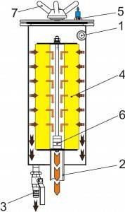
The oil purification plantCMM-2.2 (seefigure 1) consistsof oil heater 5; vacuum column 1; cartridge filters 6; gear pumps2 and 3; vacuum pump7; control cabinet 8; metal base-frame mounted on castor wheels. All subunits are connected with pipelines 4.
Casing shall be provided sides and back doors on fabricated frame works. The equipment and Control cabinet equipment can be enclosed and protected against climatic conditions. Sound and noise protection (insulation tape) is provided.
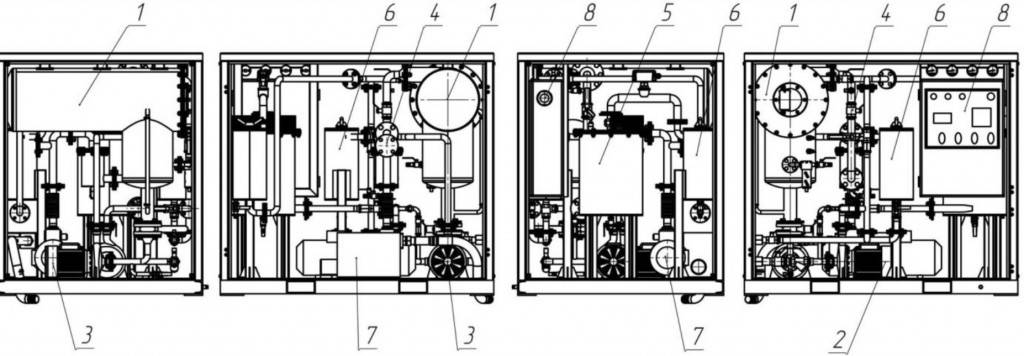
Figure1. СММ-2.2 generalview
1-vacuum column; 2-oil input pump;3-oil output pump; 4-pipe line system with stopa nd control valves; 5-oil heater; 6-fine filter; 7-vacuum pump;8-control cabinet
Oil heater 5 (see figure 1) is a cylindrical heat-insulated vessel, which contains ceramic electrical heaters (capacity 3 kW each) and equipped with inlet and outlet pipelines, as well as drainage valve. To prevent oil overheating, temperature controller sensor and thermostat are provided
in the heater.
Heater has a demountable structure to provide easy heating elements replacement.
Optionally heater can be equipped with the temperature control system (TCS) consisting of temperature controller with PID regulator “Autonics” and power regulators “Carlo Gavazzi”. This temperature control system allow to regulate the oil heating temperature by means of change of pre-sets of temperature (in 0C or 0F) and/or time of heating (in hours/minutes) using the controller’s buttons.
TCS is able to apply load gradually in order to prevent oil overheating and impulsive load on power circuit. Contact your service manager for details.
For oil heater over view watch figure 2.
Figure
2. Oil heater
1 – heating element; 2 –cold inlet oil pipe branch; 3 – heated outlet
oil pipe branch; 4 – housing;5 – tubular grid;6 – heaters block cover; 7 – thermostat;
Employ temperature control sensortocontroloiltemperature when heated.
Heaterise quipped with separate thermostat forextra-control and protection against overheating interlocked with heating elements and all electric devices of the unit.
Mesh filter is installed at the unit inlet and is designed for mechanical contaminants release. Filtration fineness isinfluencedbya 200 micron brass mesh mounted inside the case. It can be easily removed and cleaned.
Inlet and Outlet Pumps are positive displacement gear pumpswith electric drive, equipped with safety valve (max. 5 bar overpressure). Power consumption – up to 2,2 kW, Flow rate – up to 5400 LPH, Outlet pressure – 2 bar. Pumps are controlledfromthecontrolpanel.
The vacuum chamber is a cylindrical heat-insulated vessel equipped with set of microfiber coalescers installed in its upper part. Coalescers design allows for oil intensively exhaling gases and moisture.
Oil level in column remains between upper and lower limits determined during manufacturing without the need of operator’s supervision. Lower-upper level sensors control inlet-outlet pumps.
To prevent foam forming by highly saturated and watered oil at the initial stage of oil processing the vacuum column is equipped with a solenoid air release valve controlled by a foam sensor.
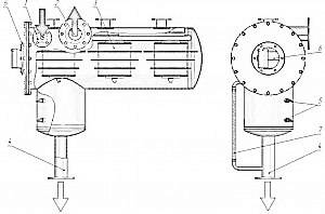
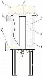
Figure 3. Vacuum column
1 – inlet branch pipe; 2 – vacuum system connecting branch
pipe; 3 – activating filter (sprayer); 4 – treated oil outlet branch; 5 – level indicator; 6 – sight glass; 7– fluid level indicator;
Inlet and outlet pipelines are equipped with coarse cartridge filter and fine cartridge filter, which also contain magnet block. Filtration fineness is2µm. The magnets should be cleaned when filter elements (cartridges) are cleaned or replaced. To eliminate air within oil gain as well as to swallow it within oil drainage, filter uses air relieve plug. Bodybottomismountedwithvalve keeping branch pipe. Inlet and outlet oil branch pipes are body welded.
The filtering elements (cartridges) are easy to replace and cleanable.
For filter general view see Figure 4.
Figure
4. Cartridge filter
1 – inlet oil pipe branch; 2 – treated oil outlet pipe branch; 3 – sludge drain valve; 4 – filtering cartridge; 5 – air release valve; 6 – magnets; 7 – clamping lever
Vacuum pump system consists of rotary wane vacuum pump CP-30 (equipped with gas ballast valve) and oil trap (equipped with oil level sensor interlocked with unit). Power consumption of the pump is up to1,5 kW,suction capacity 63 m3/h.
Control cabinet is designed for placement of electrical components to facilitate Unit operation. Itisametalcabinetwithlockabledoor. Electricalcontrolandcommutationcircuitsarepanel locatedinside.
Control buttons and light signaling devices are installed on the cabinet. The unit is controlled by PLC Mitsubishi Alpha 2 that allows to operate the unit with minimum manpower effort. It is also equipped with sound and light alarm.
By request the control cabinet can be equipped optionally with colored Mitsubishi Touch Screen Monitor 5,4”, Series GOT1000. GSM module for remote plant operation monitoring can be also optionally installed.
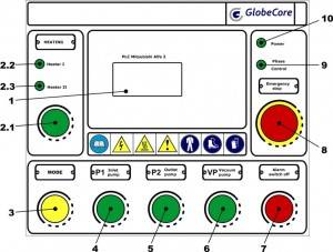
Figure
5. Control cabinet
1 – PLC Mitsubishi Alpha2; 2.1 – heating mode switch button; 2.2– 1st heating stage indicator; 2.3 – 2ndheating stage indicator; 3 – Mode switch button; 4 – Inlet pump on/off switch button; 5 – Outlet pump on/off switch button; 6 – Vacuum pump on/off switch button; 7 – Alarm switch off button; 8– Emergency stop button; 9 – Phase control indicator; 10 – Power indicator.
Inlet and outlet of coarse cartridge filter are equipped with pressure gauges with measurement range 0 – 10 bar (kgs/cm2) to control pressure and pressure differential on filter and change the filter elements in time.
Inlet of fine cartridge filter is equipped with pressure gauge (Measurement range 0 – 10 bar (kgs/cm2) to control pressure on filter.
For ultimate pressure (vacuum) indication, vacuum gauge is installed in the vacuum vessel. Measurement range -1….0 bar (kgs/cm2).
Principle of operation
CMM-2.2 plant can be operated in the following modes:
1. Oil thermo-vacuum
dehydration.
2. Filtration with heating
Operation in «Oil thermo-vacuum dehydration» mode.
Treating oil is supplied by inlet pump, through inlet valve, mesh filter, coarse cartridge filter to oil heater. After it is heated it is supplied to vacuum column activating filter (coalescer). The vacuum is maintained in chamber by the vacuum pump.The vacuum rate is regulated by adjustment valveand controlled by vacuum meter.
Inside the coalescer oil is being dehydrated and degassed. Gases and vapour are exhausted by vacuum pump through moisture separator into atmosphere. Degassed oil is pumped out by outlet pump through fine cartridge filter and non-return valve into the clean oil tank (or directly into transformer).
Operation in «Filtration with heating» mode.
Treating oil is supplied by inlet pump, through inlet valve, mesh filter, coarse cartridge filter to oil heater. After it is heated it is supplied to the vessel for purified (treated) oil. Oil is preliminary heated to the required temperature in the heater.
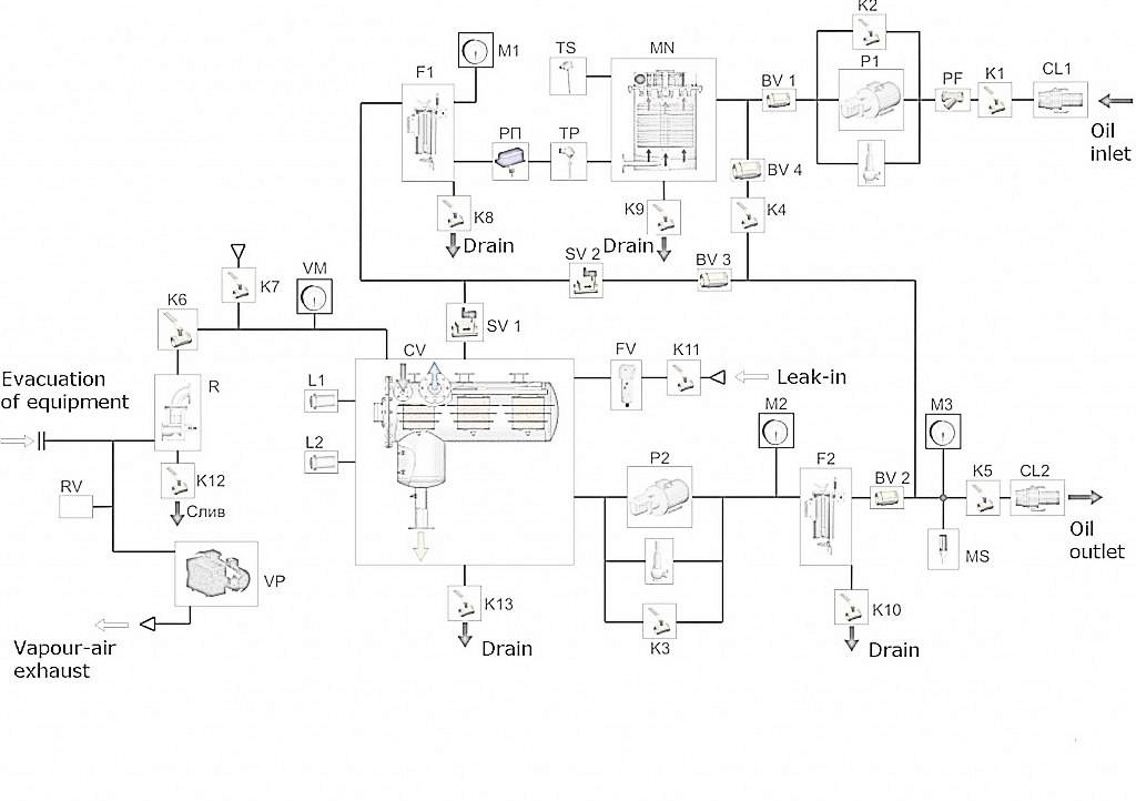
Figure6. CMM-2.2hydraulic diagram
Warranty
The Manufacturer guarantees normal and stable operation of the Unit if all installation, operation, maintenance, transportation and storage regulations, laid down in this manual, are observed.
Warranty period is 13 months from the date of shipment.
If any manufacturing defects or failure of the Unit or its components through manufacturer’s fault are uncovered during warranty period, the user is entitled to make a claim to the manufacturer without disassembling the unit or its components. In the course of five days the user draws up a preliminary act and notifies the manufacturer about the defect.
Warranty is void in case of:
- insufficient servicing and maintenance;
- insufficient operation;
- insufficient operation medias;
- Unit design alteration;
- use of defective tools;
- use of non-original spare parts;
- unauthorized alteration of the Unit or its components.