Transformer oil purification system CMM-1.0 (capacity 1000 LPH)
1. GENERAL INFORMATION
High Vacuum Transformer Oil Purification Plant model СММ-1.0 purifies insulating oils of mechanical particles and employs thermal vacuum for water and gas removal. Operate the Unit when assembling, servicing and exploiting oil filled equipment (power transformers, high voltage switches, etc.) up to 1150 kV of voltage.
Theunit maybe used for heating of oil-filledelectrical equipment by hot transformer oil, vacuum transformer drainage and transformer dry-out. Unit is used for installation, repair and maintenance companies which are dealing with transformer oil treatment.
The unit is not fit for operation in explosive or toxic environment, as well as environment reactive to lubrication materials.
When operating the unit indoors, install gas exhaust line to evacuate gases into the atmosphere.
Performance in a single pass through the
purifier at a full flow rate shall be as follows:
Water Removal: From 100 ppm down to less than 10 ppm as measured by ASTM method D-1533.
Gas Removal: From fully saturated with air (10 to 12% by volume) down to less than 0.25% by volume as measured by the ASTM Method D-2945
Particulate Matter Removal: 99.5% of particles over 2 μm
Dielectric Strength: Improvement in dielectric strength up to 70 kV.
2. TECHNICAL DATA
|
Parameter |
Value |
|
| 1. Capacity, m3/h, | ||
| – in degassing, dehydration and filtration mode |
1.0 |
|
| – in heating and filtration mode |
up |
|
| 2.Capacityadjustmentrange, m3/h |
1.0-3.0 |
|
| 3. CP 30-620 backing vacuum pump capacity, m3/h |
76 |
|
| 4. PedroGil RVB 20.20 Roots vacuum pump capacity, m3/h |
280 |
|
| 5.* Processed oil parameters : | ||
| – maximum gas content, %, max. |
0.1 |
|
| – maximum moisture content, ppm, max. |
10 |
|
| – ISO 4406 industrial purity class |
9 |
|
| – mechanical impurities content, ppm, max | 8 | |
| – filtration rating, micron | 2 | |
| -breakdown voltage, kV, minimum | 60 | |
| 6. Maximumoiloutlettemperature in heating mode , ºС |
90 |
|
| 7. Filtration coefficient |
>50 |
|
| 8.Outlet pressure, MPa |
0.35 |
|
| 9. Delivery head, m |
35 |
|
| 10. Oil heater power, kW |
50 |
|
| 11. Oil heater mean power, W/cm2, max |
1.15 |
|
| 12. Maximum power consumption, kW, max. |
60 |
|
| 13. Power supply parameters, 3 Phases |
|
|
| – voltage, V |
380 |
|
| – AC frequency, Hz |
50 |
|
| 14. Dimensions w/o trailer, mm, max. |
|
|
| – length |
1650 | |
| – width |
1250 |
|
| – height |
1590 |
|
| 15. Weight, kg, max. |
920 |
|
Note – *For inlet oil parameters as follows:
- gas content by volume lessthan 10,5%
- moisture content by weight lessthan 0,01% (100 ppm)
- temperature above 0 ºС.
3. TECNICAL DESCRIPTION OF THE EQUIPMENT
3.1 Configuration
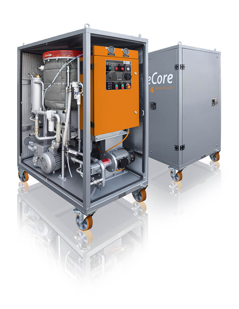
3.1.1. The Unit (figure1.1) is an assembled container keeping all the junctions, components and aggregates. Container can be one- or biaxial trailer mounted. Front as well as back wall is lockable doors mounted for unobstructed access and fanning. Unit is supplied mounted on trailer equipped by torsional suspension axels, pneumatic wheels, coupling loop, support jacks, pneumohydraulic braking system, parking brake hand lever and electrical equipment.
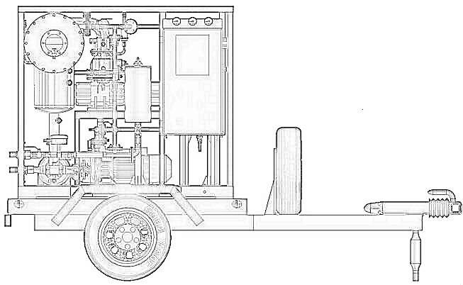
Figure 1.1. Unit general view (trailer as option)
There are the following components inside the frame: vacuum column 1, inlet oil pump 2, outlet oil pump 3, oil heater 5, fine filters 6, control panel (complete control unit CCU), vacuum pumps cluster 7 and 8, pipeline system with shutoff and control valves 4. To adjust parameters, Unit employs temperature controller «Autonics» (equipped with ТСМ sensors), vacuum controller «Autonics» (equipped with Sapphire vacuum sensor), both pressure and vacuum gauges (М1-М3).
3.1.2. Vacuum pumps cluster (figure 1.2) is a frame mounted with one backing pump 7 and
one vacuum booster pump (Roots pump) 8. Capacity of backing vacuum pump CP30-620 is 76 m3/h and it is capable of decreasing to 0,5 mbar vacuum level. Capacity of Roots pump Pedro Gil RVB 20.20 is 280 m3/h and it is capable of decreasing to 0,01 mbar vacuum level. Vacuum pumps cluster joins vacuum column and oil trap as well as vacuum pipeline which is shut-off valve equipped.
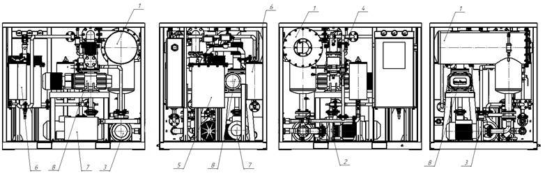
Figure1.2 – Unit general view: 1 – vacuum column, 2 – input pump, 3 – output pump, 4 – pipeline system, 5 – oil heater, 6 – coarse and fine filters, 7 – vacuum backing pump СР30-620, 8 – booster (Roots) pump RVB-20.20.
3.1.3. Mesh filter is installed at the unit entrance and is designed for mechanical contaminants release. Filtration fineness isinfluenced by a 200 micron brass mesh mounted inside the case. It can be easily removed and cleaned.
3.1.4. Centrifugal Pumps NM3/A made by Calpeda 2 and 3 supply transformer oil into the Unit and suck it out respectively. The pumps are controlled from the control panel.
3.1.5. Coarse and fine filters 6 purify the oil being processed. Filtrationfinenessof both filters is 2 micron.
The filter is lid and frame keeping one filtering cartridge and magnets inside. Filtering cartridges are made of EFMG filtering elements. To eliminate air within oil gain as well as to swallow it within oil drainage, filter uses air relieve plug. Body bottom is mounted with valve keeping branch pipe.
Inlet and outlet oil branch pipes are body welded.
The filtering elements (cartridges) as well as magnets are easy to replace and cleanable.
3.1.6. Oil heater 5 (figure 1.2) is a chamber keeping band heating cluster, inlet and outlet pipelines, as well as drainage valve.
Use separate control switch button to manage overall cluster. Heater is equipped with the temperature control system (TCS) consisting of temperature controller “Autonics” and one-stage heating element. Optionally unit can be equipped with PID regulator “Autonics” and power regulators “Carlo Gavazzi”. This temperature control system allows to regulate the oil heating temperature by means of change of pre-sets of temperature (in 0C or 0F) and required time of heating (in minutes/hours) using the controller’s buttons.
TCS is able to apply load gradually in order to prevent oil overheating and impulsive load on power
circuit.
Employ temperature control sensor Th1 (Figure 6) to control oil temperature when heated.
Flow relay PП indicates operational fluid flow to prevent heating section failure and oil overheating. Heater is interlocked by a flow switch and is being energized only when oil is flowing through it. Heater is equipped with separate thermostat TS for extra-control and protection against overheating interlocked with heating elements.
3.1.7. Vacuum column 1 (figure 1.2) is designed for degassing of transformer oil.
A shut-off valve is installed at the column for connection of vacuum system. Vacuum column includes also vacuum sensor VG, as well as level sensors L1 – L3.
Residual pressure of no more than 267 Pa is maintained in the column in the process of oil degassing. Oil is transported to the column by inlet pipe and through the collector to the activating filters (sprayers).
Sprayer design allows for oil intensively exhaling gases and moisture.
Oil level in column remains between upper and lower limits determined during manufacturing without the need of operator’s supervision. Lower-upper level floats control inlet-outlet pumps.
To prevent foam forming by highly saturated and watered oil at the initial stage of oil processing the vacuum column is equipped with a solenoid valve controlled by a foam sensor.
3.1.8. Control cabinet is designed for placement of electrical components to facilitate Unit operation. For control cabinet general viewwatch figure 2.
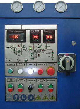
Figure 2. General view of control cabinet panel
3.1.9. Control and measurement instruments. Column’s residual pressure is controlled by Autonics electronic vacuum controller. Limit of effective measuring range is 50 Pa.
When operated the unit is controlled by following measuring gauges:
thermostat – for oil heater switch off if oil temperature is above 90 ºC set;
- flow relay – for oil heater switch off if no oil flow is supplied through oil heater;
- thermistor – for oil temperature measuring on heater outlet;
- manometers – to indicate contamination level of filter elements with regard to difference of inlet and outlet pressure in fine filters;
- level indicators – to control oil level in vacuum column;
- oil-in-trap indicator – to prevent oil inlet into the vacuum system and vacuum pumps damage.
When power disconnected electromagnetic valve SV1 blocks oil support at the vacuum tank input.
3.2. Principle of operation.
Schematic hydraulic diagram is given on figure 3.
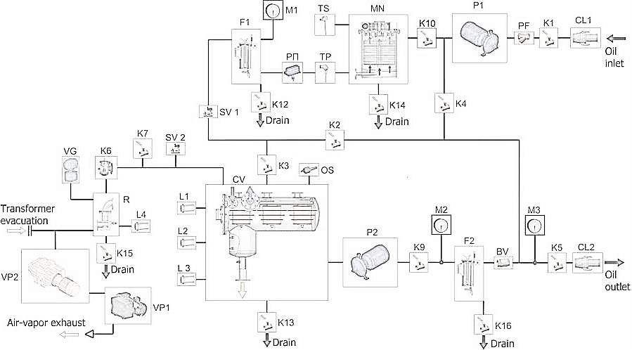
Figure 3.- Schematic hydraulic diagram
СV – vacuum column; P1 – oil inlet pump; P2 – oil outlet pump; K1 – K5, K7, K9 – K16 –
ball valves; K6 – vacuum valve; MN – oil heater; BV – non-return valve; F1 – coarse filter; F2 – fine filter; М1,М2,М3 – manometers; ТP – temperature measuring sensor; TS– thermostat; PП –
flow relay; SV1 – SV2 – electromagnetic valves; VG – vacuum sensor; L1– L4– level sensors; VP1 – vacuum pump; VP2– booster (Roots) vacuum pump; РF1 – mesh filter; R – oil trap; OS – foam sensor.
3.2.1. The unit can be operated in the following modes:
- oil heating and filtration;
- oil dehydration and degassing;
- vacuumizing of external equipment;
- degassing unit during oil regeneration process (available additional quick couplings for oil outlet/inlet when using Fuller’s earth columns ZP-260 for oil regeneration process);
- oil pumping.
Level sensor L4 is mounted in the oil trap R1 to prevent oil (foam) entry to vacuum system. When oil or foam is detected in vacuum system the alarm sounds and system stops automatically inlet pump P1 and vacuum pumps VP1, VP2. Electric valve EV1 blocks oil supply at the vacuum tank input. Electric valve EV2 is being opened to release pressure from column for foam removing.
When power disconnecting electromagnetic valve SV1 blocks oil supply at the vacuum tank input.
3.2.2. In transformer oil pumping mode untreated oil is supplied to the Unit output through mesh filter РF1 by means of oil pump P1 through ball valves K1, K4, K5.
3.2.3. In transformer oil heating and filtration mode untreated oil is supplied to the Unit output by means of oil pump P1 through ball valve K10, oil heater MN, cartridge filter F1, boll valve K2, K5. In transformer oil heating mode (6 m3/h is maximum capacity) oil heater is switched on. After oil treatment is finished, turn OFF oil heater MN, and after 5 min close all opened valves, switch OFF pumps P1, P2.
3.2.4. Transformer oil degassing is carried out by means of thermal vacuum treatment.
To degas oil as well as to purify it of mechanical contaminants perform as follows.
Transformer oil is supplied to mesh filter PF, through the oil heater MN to coarse cartridge filter F1.
Heated up to 50…55ºС and filtered of mechanical contaminants oil is supplied to vacuum column CV through employing ball valve K3 and then to the filter activators (sprayer) through the collector. Dissolved gases and moisture have been eliminated from oil in a process of spraying through filter activators.
Vacuum inside vacuum column is arranged by vacuum pumps. Residualpressure (up to 267 Pa), generatedinvacuumcolumn, allows to get required oil quality.
Pump P2 transfers oil from column to transformer through fine cartridge filter F2, ball valve K5 and return valve SV.
The Unit allows heating and adjusting modes to exclude a low-quality oil supply at initial operating stage. For adjusting mode fill vacuum column with transformer oil, then heat the Unit with hot oil circulating by circuit:
- vacuum column СV;
- oil pump P2;
- cartridge filter F2;
- ball valve K4;
- cartridge filter F1;
- oil heater MN;
- ball valve K3 which sets required capacity for oil supply into the spray to manage residual pressure in vacuum column up to 267 Pa(2 mm Hg).
After oil treatment is finished, turm OFF oil heater MN, and after 5 min close all opened valves, switch OFF pumps P1, P2, VP2.
3.2.5. Transformer vacuumizing is performed by pumps VP1 and VP2 through the pipe branch for vacuumizing of external equipment.
3.2.6. Processing of transformer oil with the regeneration plants/Fuller’s earth columns ZP-260 is made as follows (additional inlet/outlet valves K17 and K18 are not shown in hydraulic diagram, can be ordered optionally). The processing insulating oil is supplied by inlet oil pump P1 through the preliminary mesh filter PF, to the heater MN and then to oilfiltercartridge F1. Heated to a temperature +50 … +55 ºC and purified from solid contaminants oil is supplied through aball valve K17 to the recycling (regeneration) plant or column. Recycled oil will be supplied than through the valves K18 and K3 to the vacuum column CV and comes through the filter-activators (sprayers). When the oil flows through the sprayer it is released from dissolved gas and moisture.
Treated, regenerated and decolorized oil is supplied then through the filter cartridge F1 by means of outlet pump P2 to the oil outlet.
3.2.7. Electric diagram is given by request in addition Annex.
The diagram provides for protection from shortcircuiting of power contours, motor circuits, lighting and heating circuits, control and outlet circuits, protects motors from overloads using thermal
relays.
The relay type НРN-51 prevents unit operation at inverse phase sequence or if phase loss occurs. Thediagramprovides blocking of oil heater operation when oil flow is absent.
Level indicator relay maintains the required vacuum column oil level.
4. WARRANTY
The Manufacturer guarantees normal and stable operation of the Unit if all installation, operation,
maintenance, transportation and storage regulations, laid down in this manual, are observed.
Warranty period is 12 months from the date of shipment.
If any manufacturing defects or failure of the Unit or its components through manufacturer’s fault are uncovered during warranty period, the user is entitled to make a claim to the manufacturer without disassembling the unit or its components. In the course of five days the user draws up a preliminary act and notifies the manufacturer about the defect.
Warranty is void in case of:
- insufficient servicing and maintenance;
- insufficient operation;
- insufficient operation medias;
- unit design alteration;
- use of defective tools;
- use of non-original spare parts;
- unauthorized alteration of the Unit or its components.