Transformer oil purification system CMM-0.16 (capacity 160 LPH)
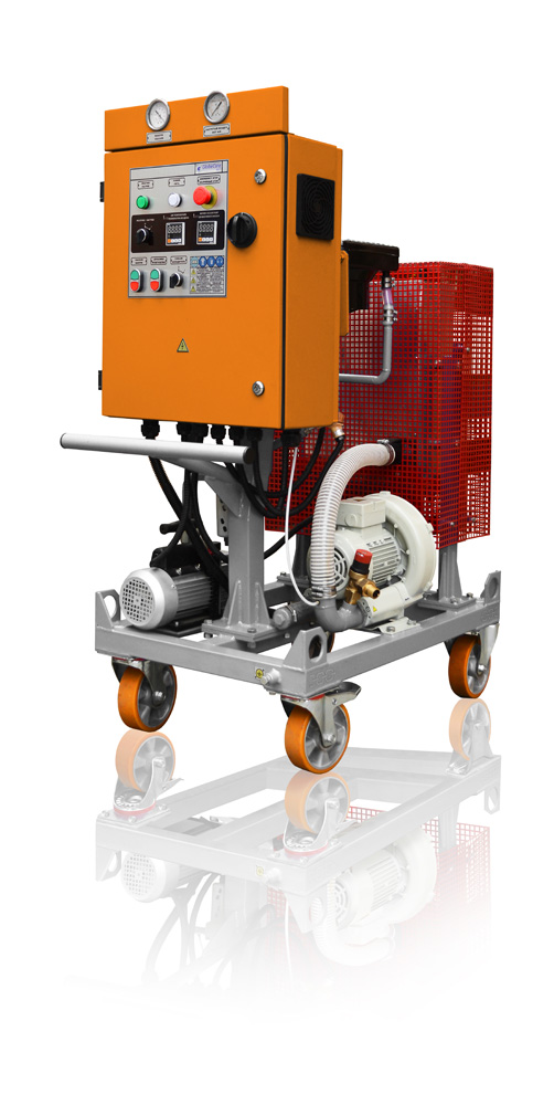
General view of the
CMM-0.16
APPLICATION OF THE OIL PURIFICATION PLANT
Every company, activities of which are related to using of oil-insulated high voltage
equipment (transformers, high-voltage switches, turbines, etc., share the problem of change or disposal of contaminated transformer oils.
Costs of disposal or changing of insulating oils are frequently very high and need a significant investment. Our equipment offers a practical, proven and economical method to purify the oil and use it again for high voltage equipment.
Most frequently encountered contaminants in oil are water, gases and solids. These contaminants
are detrimental to the performance and life of the oil. Oil purification equipment produced by GlobeCore is intended for purification of oils by means of thermo-vacuum process. Oil purification unit is fully acceptable for the following oils:
•Insulating (Transformer Oils)
•Lubricating Oils
•Turbine Oils
•Compressor Seal Oils
•Synthetic Fluids
•Cutting and Cooling Mineral Oils
Operational conditions:
• Oil viscosity must not exceed 70 centistokes at 50oC.
•Ambient temperature in the range from 0 to 35oC (273 to 308K);
•Atmospheric pressure from 84 to 106.7 kPa (630 to 830 cm. hg.);
•Height above mean sea level up to 2000 m;
•Fire-proof and ex-proof building.
SHORT PROCESS DESCRIPTION
The unit can operate in one of two modes:
- filtration
- hot filtration and thermo-vacuum drying
Filtration mode
Gear pump sucks the oil for processing via valve and strainer. Processed oil is then pumped through cartridge filter, three-way valve and is discharged to processed oil vessel via connector.
Hot filtration and thermo-vacuum drying
Gear pump sucks the oil for processing via strainer and cartridge filter and directs it to the heat exchanger, where the oil is heated by the circulating heat conductor. The oil is fed to the vacuum chamber after being heated to 60oC. Vacuum pump maintains vacuum in the vacuum chamber. Vacuum can be regulated by valve and monitored on the vacuum meter. Filtered hot air comes into the chamber and removes gases and vapor from the oil’s surface, drying the oil. The air is then discharged into the atmosphere via oil separator by the vacuum pump. Gear pump directs the oil into the processed oil vessel. A programmable thermal regulator switch monitors the plant’s function continuously and maintains the pre-set temperature.
SCOPE OF SUPPLY, DESIGN AND SPECIFICATIONS
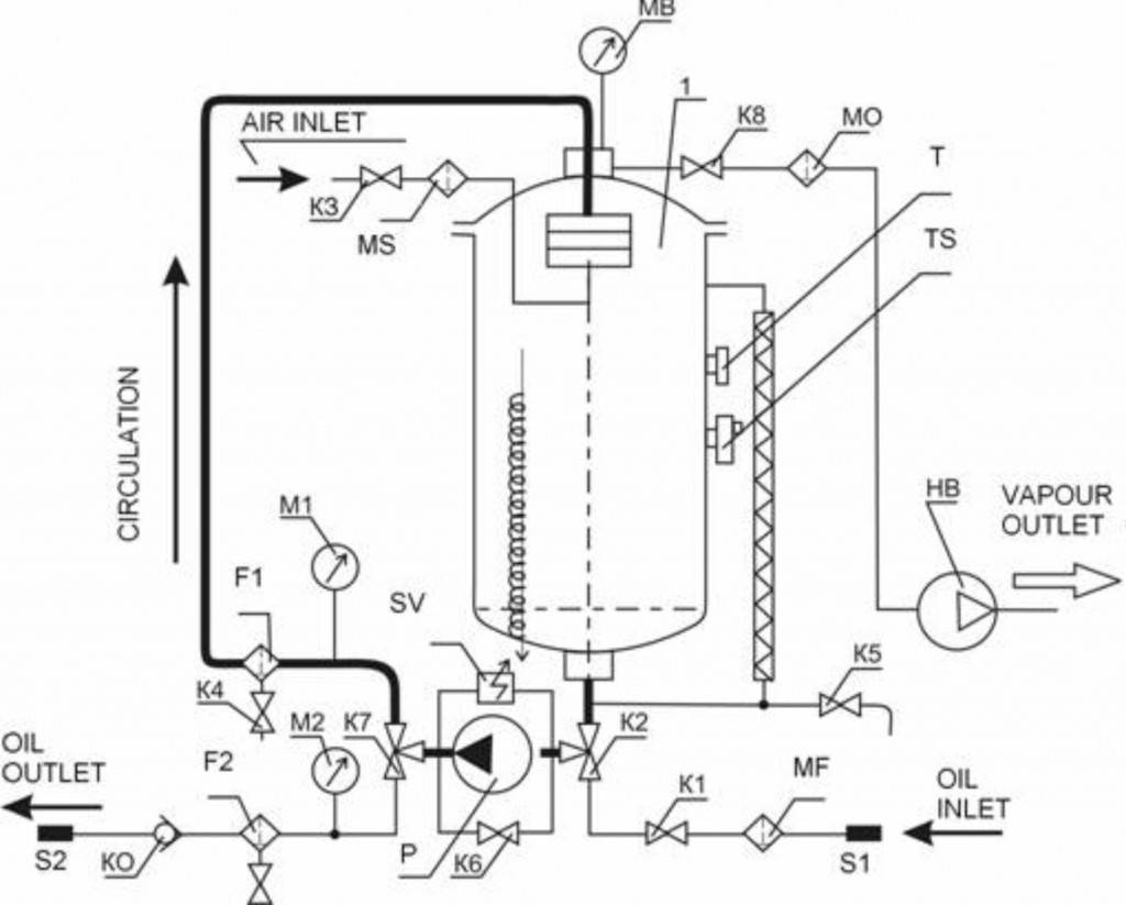
1 – vacuum chamber;P– gear pump; VP – vacuum pump; МV – vacuum gauge; М1÷М2 –
pressure gauges F1 – coarse filter; F2 – fine filter; MF – mesh filter; SV– safety valve; KO– return valve;FA – moisture separator; МО – oil separator; Т – bimetallic thermometer; ТS– thermostatК1 – inlvet valve DN20; К3÷К5 – drain valves DN15; К6 – by-pass valve DN15;К2, К7 – three-way ball valves DN15; S1 – oil inlet sleeve; S2 – oil outlet sleeve
Oil parameters after treatment
| Oil before treatment |
Oil after treatment |
|
| Humidity content |
50 ppm | ≤ 5 ppm |
| Gas content |
10% | ≤ 0,35 % |
| Filtration fineness |
5 µm |
*By removing of water, particulate matter and gases breakdown voltage is guaranted to be 65 kV
Specifications:
| Type | CММ-0,16 |
| Performance | Mobile, mounted on rollers, equipped with break |
| Capacity | in summer time 160 l/h, in winter time 80 l/h |
| Rating | Batch operation |
| Supply Power Source | AC, 3 Phase, 4 wire, 400 V, 50 Hz (as per clients requirement) |
| Motors | Oil circulation pump: 0,75 kW Vacuum pump: 0,25 kW |
| Oil temperature | 55…65oC (adjustable) |
| Operating vacuum | -0,85…-0,95 bar |
| Pre-filter | 0,75 ммmesh wire screen basket type |
| Oil inlet and outlet pumps | Oil circulation is a gear pump, driven by 0,75 kW motor, rated at 1440 rpm Oil exhaust pump is equipped with a water-gate to prevent infusion of outside air. |
| Heate | ТЭН is an assembly consisting of metallic case, designed from tube of corresponding diameter. There is a nichrome wire coil inside of case. Wire edges are connected to contact bar. Ceramic insulator is mounted between tube flank and contact bar. Inside space is filled with filling compound, which has a high dielectric property and high heat conductivity (crystal magnesium oxide – Mq O). |
| Heating power | 4,8 kW |
| Filter 1 | In welded design, vacuum and pressure-tight, complete with cover and easily exchangeable filter cartridge – filter cartridge, 15 µ |
| Vacuum chamber | In welded design. Heat-insulated from outside. |
| Filter 2 | In welded design, vacuum and pressure-tight, complete with cover and easily exchangeable filter cartridge – filter cartridge, 5 µ |
| Attachments | – Filter clogging monitoring system (pressure gauge 0 – 10 kg/sm2) Air inlet Vacuum trap – in welded design, vacuum and pressure tight. |
| Vacuum pump | – Rotary vane vacuum pump, driven by motor |
| Ultimate vacuum | 0,5 mbar |
| Valves | DN15 – 9 pcs |
| Measuring device | To prevent heat-conductor overheating, the control circuit is equipped with thermal regulator switch sensors. Processed oil temperature is set with regulating control device, which maintains the value automatically |
WARRANTY and EC DECLARATION of CONFORMITY
By adherence of all technical operational conditions, mentioned in technical passport and operation manual – warranty period for supplied Goods – 12 months from the putting into operation period, no more than 18 months from the sale period.