High vacuum transformer oil reclamation degassing plant CMM-10 (capacity 10 000 LPH)
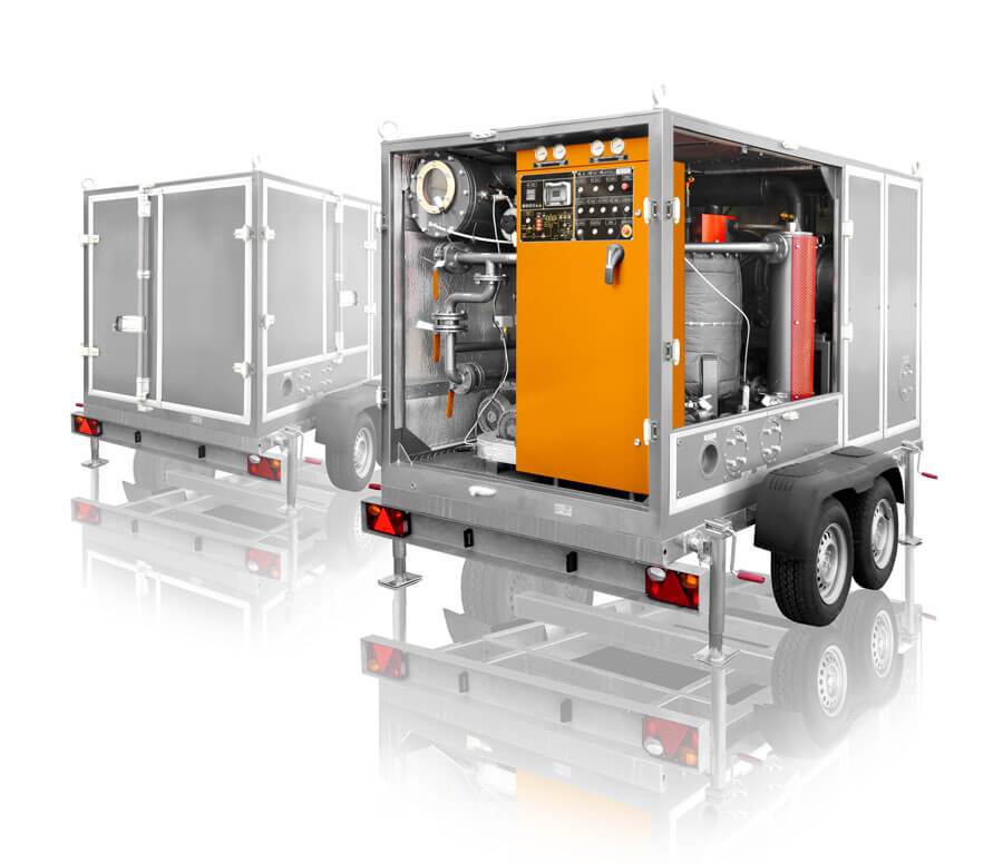
CMM-10.0 General view of reclamation system for transformer’s cooling agent
1. GENERAL INFORMATION
High Vacuum Transformer Oil Purification Plant model СММ-10.0 purifies insulating oils of mechanical particles and employs thermal vacuum for water and gas removal. Operate the Unit when assembling, servicing and exploiting liquids filled equipment (power transformers, high voltage switches, etc.) up to 1150 kV of voltage.
When running closed space operation consider pipelines exhausting gases extracted into the atmosphere.
Performance in a single pass through the purifier at a full flow rate shall be as follows:
Water Removal: From 50 ppm down to less than 5 ppm in a single pass and down to 3 ppm after several passes as measured by the ASTM Method D1533
Gas Removal: From fully saturated with air (10 to 12% by volume) down to less than 0.1% by volume as measured by the ASTM Method D-2945
Particulate Matter Removal: 98% of particles over 1 μm
Dielectric Strength: Improvement in dielectric strength up to 70 kV.
2. TECHNICAL DATA
|
Parameter |
Value |
|
|
1. Capacity, m3/h |
||
|
– in degassing, drying and filtration modes |
10 |
|
|
– in heating and filtration modes |
16 |
|
|
2. Processed oil parameters*: |
||
|
– maximum gas content by volume, % |
0.1 |
|
|
– maximum moisture content by mass, ppm |
5 |
|
|
– filter fineness, micron |
2 |
|
|
3. Maximum outlet oil temperature in heating mode, ºС |
90 |
|
|
4. Booster vacuum pump capacity, m³/h |
2160 |
|
|
5. Outlet pressure, MPa |
0.4 |
|
|
6. Oil heater power, kWt |
180 |
|
|
7. Maximum power consumption, kWt |
210 |
|
|
8. Vacuum column max. residual pressure in degassing mode, Pa |
267 |
|
|
9. Vacuum column max. residual pressure at air tightness, Pa |
26.7 |
|
|
10. Maximum inleakage within 1 hour of vacuum tightness check, Pa |
267 |
|
|
11. Voltage parameters, 3 Phase+N |
||
|
– voltage, V |
380 |
|
|
– AC frequency, Hz |
50 |
|
|
12. Max. overall dimensions (with trailer), mm |
||
|
– length |
4750 |
|
|
– width |
2100 |
|
|
– height |
2320 |
|
|
13. Max. weight, kg |
3500 |
*Note – For initial inlet oil parameters as follows:
– gas content by volume less 10,5%
– moisture content by weight less 0,01% (100 ppm)
– while heating liquid in the unit to +50±50 C for at least 30 minutes.
Scope of supply
|
Item |
Quantity |
|
1. Mobile high vacuum transformer oil purification plant model CMM-10.0 mounted on double axial roadworthy trailer with metal weatherproof container |
1 |
|
2. Flow totalizer BellFlow™ |
1 |
|
3. Foam regulation system |
1 |
|
4. Flexible stainless steel oil hoses with quick connectors, L=15m |
2 |
|
5. Flexible stainless steel vacuum hose, flanged, L=10m |
1 |
|
6. Set of spare parts for 3 years operation |
1 |
|
7. Operation and maintenance manual in English (written) |
8 |
|
8. Operation and maintenance manual in English (soft copy on CD) |
4 |
Set of spare parts for 3 years operation
|
№п/п |
Наименование |
Unit |
Qty for 3 years operation |
|
1 |
Filler 10×3000 (for vacuum column) |
Pcs. |
2 |
|
2 |
Filler 10×1700 (for oil heater) |
Pcs. |
3 |
|
3 |
Sealing ring 010-015-30 GOST 9833 |
Pcs. |
27 |
|
4 |
Sealing ring 024-030-36 GOST 9833 |
Pcs. |
27 |
|
5 |
Sealing ring 065-075-58 GOST 9833 |
Pcs. |
6 |
|
6 |
Sealing ring 110-120-58 GOST 9833 |
Pcs. |
6 |
|
7 |
Sealing ring 180-195-85 GOST9833 |
Pcs. |
6 |
|
8 |
Sealing ring 023-029-36 GOST9833 |
Pcs. |
6 |
|
9 |
Activating filter (vacuum column) |
Pcs. |
40 (1 complete set) |
|
10 |
Vacuum oil, VC class, acc. DIN 51506: ESSO Series TELESSO; Shell Series Talpa G |
Liter |
14 |
|
11 |
Filter cartridge 2 micron |
Pcs. |
12 |
|
12 |
Non-return valve DN40 |
Pcs. |
1 |
|
13 |
Spare parts for Booster vacuum pump |
||
|
Sealing ring 045-051-167 |
Pcs. |
6 |
|
|
Sealing ring 185-195-58 |
Pcs. |
3 |
|
|
Sealing ring 210-220-36 |
Pcs. |
3 |
|
|
Sealing ring 215-225-58 |
Pcs. |
9 |
|
|
14 |
Centrifugal pump ring set |
||
|
Sealing ring 088-092-25 |
Pcs. |
12 |
|
|
Sealing ring 102-108-25 |
Pcs. |
12 |
|
|
15 |
Unit ring set |
||
|
Sealing ring 145-150-36 |
Pcs. |
6 |
|
|
Sealing ring 056-066-58 |
Pcs. |
12 |
|
|
16 |
– for oil drain; PVC hose DN20: – for oil feeding from tank; – for oil feeding from tank |
Meter |
1 |
|
Meter |
3 |
||
|
Meter |
5 |
||
|
17 |
PVC hose DN25 for oil drain |
Meter |
1 |
|
18 |
Electric components |
||
|
Auxiliary contact В1 |
Pcs. |
4 |
|
|
Auxiliary contact В2 |
Pcs. |
4 |
|
|
Relay MY3 AC 220В with socket |
Pcs. |
4 |
|
|
Relay MY3 DC 24 В with socket |
Pcs. |
4 |
|
|
Actuator PM 1-18 |
Pcs. |
2 |
|
|
Actuator PM 2-32 |
Pcs. |
2 |
|
|
Actuator СЕМ 95 |
Pcs. |
2 |
|
|
Capacitive probe Carlo Gavazzi EC3016PPASL |
Pcs. |
2 |
|
|
On/Off switch |
Pcs. |
2 |
|
|
Lighting red |
Pcs. |
9 |
|
|
Vacuum column light |
Pcs. |
1 |
|
|
19 |
Instrumentation |
||
|
Manifold pressure gauge |
Pcs. |
2 |
|
|
Vacuum-sensing instrument RVE with vacuum lamp |
Pcs. |
6 |
|
|
OWEN 2-channel |
Pcs. |
2 |
|
|
Temperature sensor ТСМ |
Pcs. |
1 |
|
|
20 |
Ball valve DN15 |
Pcs. |
3 |
|
21 |
Oil filter for vacuum pump CP40-620 |
Pcs. |
3 |
|
22 |
Hose “Food” flanged DN60 for vacuum system, 5 meters |
Pcs. |
1 |
|
23 |
Oil hose with cam-lock connectors DN50, 10meters |
Pcs. |
2 |
|
24 |
Pipe TRN 6/4, 5meters |
Pcs. |
1 |
|
25 |
Hexagon socket wrenches set 1,5-10, 12. |
Pcs. |
1 |
|
26 |
Pin-face (spanner) wrenches set 6-32, 32/36 |
Pcs. |
1 |
|
27 |
Adjustable wrench 0-46mm |
Pcs. |
1 |
|
28 |
Open-jawed wrench №2 |
Pcs. |
1 |
|
29 |
Screw drivers set (straight-blade and cross-blade) |
Pcs. |
1 |
|
30 |
Heavy-duty straight-blade screwdriver |
Pcs. |
1 |
|
31 |
Tap wrench for filters (house made) |
Pcs. |
1 |
|
32 |
Oil-pot with tube (for vacuum pumps oil servicing) |
Pcs. |
1 |
|
33 |
Visual observation mirror for hard-to-reach places |
Pcs. |
1 |
|
34 |
Tool kit box |
Pcs. |
1 |
3. UNIT TECHNICAL DESCRIPTION
3.1 Unit design of Mobile Type Transformer Oil Purification Plant
3.1.1 The Unit for oil reclamation (figure1.1) is an assembled container keeping all the junctions, components and aggregates. Container is the one biaxial trailer mounted. Side as well as back wall is flap door mounted for unobstructed access and fanning. Gas springs are employed to open the doors. Unit is supplied mounted on two-axial trailer equipped by torsional suspension axels, pneumatic wheels, coupling loop, support jacks, pneumohydraulic braking system, parking brake hand lever and electrical equipment.
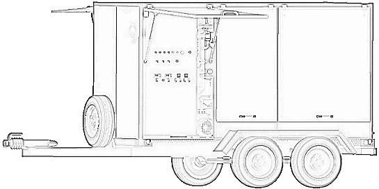
Figure 1.1 Mobile Type Transformer Oil Purification Plant overview
The Unit performs vacuum chamber (column) 1, inlet liquid pump 2, outlet liquid pump 3, coarse (preliminary) filter 4, finefilters 5, fluid trap 6, dielectric heater 7, pipelines mounted with shut-off valves and adjusting fittings, vacuum pumps cluster and control cabinet 8 as well.
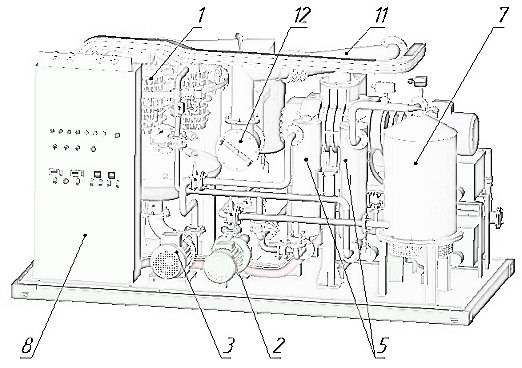
Figure 1.2 Front view of Mobile Type Transformer Oil Purification Plant
Vacuum pumps cluster (figure 1.3) is a frame mounted with three backing pumps 9 and vacuum booster pump (Roots pump) 10. Vacuum pumps cluster joins vacuum column 1 and oil trap 6 as well as vacuum pipeline 11 which is shut-off valve equipped. Pumps expulsion pipes splice into overall collector 13 to approach outer rear wall of container.
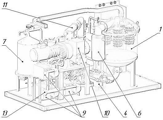
Figure 1.3 Rear view of reclamation system
To adjust parameters, Unit employs temperature controllers 2ТRМ «Оven» (equipped with ТСМ sensors), vacuum controllers RVE-4,1 (equipped with PМТ-6 lamps), both pressure and vacuum gauges(М1-М4).
3.1.2 Unit input is mesh coarse filter 4 equipped to purify oil of mechanical contaminants. Filtration fineness is caused by body fixed brass mesh of 200 micron cells. To wash filtering element remove mesh filter off the body and rinse it with clean transformer oil. For filter overview watch figure 2.
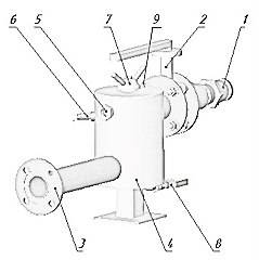
Figure 2 Coarse preliminary filter
1 – inlet oil branch pipe;
2 – shut-off valve (butterfly-type);
3 – outlet oil branch pipe;
4 – filter body;
5 – visual liquid indicator (for oil level control);
6 – liquid level sensor;
7 – clamping lever of filter lid;
8 – sludge drain valve
9 – air release plug
3.1.3 Pump 2 supplies transformer oil into the Unit while pump 3 sucks it back. To manage pumps, use control unit.
3.1.4 Fine filters 5 (figure 1.2) filter the dielectric to be treated. Filtration fineness is 2 micron. For filter overview watch figure 3.
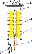
Figure 3 Fine filter of filtration unit
1 – inlet oil branch pipe;
2 – outlet purified oil branch pipe;
3 – sludge drain valve;
4 – filtering cartridge;
5 – air release plug;
6 – magnets;
7 – clamping lever.
The filter is lid and frame keeping two filtering packages inside. Filtering packages are made of EFMG filtering elements. To eliminate air within oil gain as well as to swallow it within oil drainage, filter uses air relieve plug. Body bottom ismounted with valve keeping branch pipe. Inlet and outlet oil branch pipes are body welded.
The filtering elements (cartridges) are easy to replace and cleanable.
3.1.5 Oil heater 7 (figure 1.2) is a chamber keeping 3-sections heating cluster, inlet and outlet pipelines, and drainage valve. For oil heater overview watch figure 4.
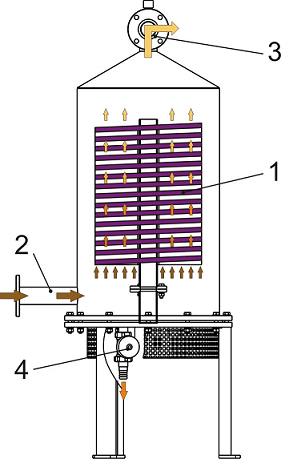
Figure 4 Heater
1 – 3-stage heating cluster;
2 – inlet cold oil branch pipe;
3 –outlet hot oil branch pipe;
4 – drainage valve
Use separate control switch buttons for each of three heating stages to manage overall cluster. Operate either each separate or any two parallel heating sections as well as all sections simultaneously (mode capacity results in operating section; thus, one or two stages are sufficient for degassing mode as long as heating and filtering mode supposes three-stage operating).
Employ temperature control sensor Th1 to control oil temperature when heated.
Flow relay FR indicates operational fluid flow to prevent heating section failure and oil overheating. Heater isinterlocked by a flow switch and is being energized only when liquid is flowing through it. Heater is equipped with separatethermostat TR for extra-control and protection against overheating.
3.1.6 Vacuum column 1 (figure 1) efficiently dries and degasses under vacuum the transformer oil by the thin-film principle. It performs body 1, cover 2, oil spray system 8, inspection window 6 and liquid indicator 11 for visual oil level control as well as oil level sensors 7 (figure 5). Ball valve 10 gains air in if necessary.
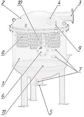
Figure 5 Vacuum column
1 – body;
2 – cover;
3 – vacuum system joining branch pipe;
4 – inlet oil branch pipe;
5 – treated oil outlet branch pipe;
6 – inspection window;
7 – liuid level sensors;
8 – polypropylene sprayers;
9 – vacuum sensor;
10 – air input valve;
11 – oil indicator.
Column (see fig. 5) is mounted with oil trap (see fig. 6 for general view) which joins vacuum valve to get vacuum system connection, vacuum sensor VR1 (9) and liquid level sensors L1 – L3 (7) as well as foam detection system. Whiledegassing oil, manage residual pressure less 267 Pa inside the column. Once supplied by pipe to the column, oil streams to oil collector and sprayer system. Sprayer design allows for intensive moisture and gases discharge.
3.1.7 Oil trap 6 (figure 1.3) prevents vacuum system of treated oil entrance. For trap overview watch figure 6. Trap isa metal case 1 welded with branch pipes to join vacuum column 2 and vacuum valve 3. The case keeps liquid indicator 4, oil level sensor 5, emergency vacuum release solenoid valve 6 and oil drainage valve 7 placed in lower section.
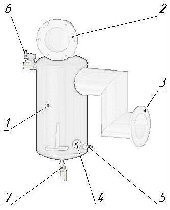
Figure 6 Oil trap
1 – case;
2 – vacuum column joint branch pipe;
3 – vacuum valve joint branch pipe;
4 – coolant visual indicator;
5 – oil level sensor;
6 – emergency vacuum releasesolenoid valve;
7 – drainage valve
3.1.8 Control cabinet supposes allocation of electrical elements allowing for Unit’s operation. It is a metal case with lockable doors and is so located that the operator can stop, start and monitor all motors from this panel and to control the equipment. All necessary instruments to monitor the complete process are located on the control panel. Cabinet’s inside panel contains electrical control and commutation circuits. Unit control switches and buttons as well as light alarm are installed on the cabinet. Upper section keeps space for power supply cabling. Pressure controllers to indicate fine filters pressure are top panel mounted.
The Unit incorporates a main power disconnecting switch and complete electrical protection arrangement. All electrical equipment is connected to a common ground which in turn is brought to a suitable terminal on the outside of the trailer.
Motor starters as well as heater switch are equipped with thermal overload relays for motors/heater protection.
All wiring is made in flexible protective conduit.
For cabinet panel overview watch figure 7.
3.1.9 Double stage Vacuum system consists of rotary-piston booster pump in conjunction with three rotary gasballasted backing pumps. Suction capacity of the Vacuum system is 2160 m3/h. It performs the following basic functions:
- drying and degassing the transformer oil;
onsite evacuation and drying of solid insulation of HV transformers.
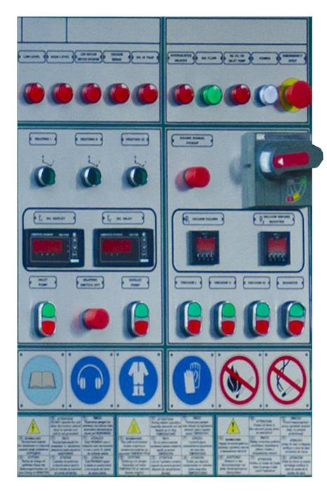
Figure 7: Overview of Cabinet automation panel of purifier
3.1.10 Controllers
Column residual pressure is controlled by electronic vacuum controller RVE-4.1. Limit of effective measuring is0,133÷105 Pa.
Oil heater operation is managed by following controllers (see fig 8 and 1.2):
-
thermostat TR to break heater at oil temperature over 70-90 ºC deemed as a value set;
-
flow relay FR to break heater at poor oil flowing through oil heater 7;
-
temperature controller Th1 to measure treated coolant temperature at oil heater outlet 7;
-
pressure gauges M1 – M4 to indicate fine filters contamination rate as well as Unit outlet pressure;
-
vacuum electronic controller RVE-4,1 with vacuum sensors VR1, VR2 to control vacuum level;
-
level sensors to control oil level in coarse filter, vacuum column and oil trap.
3.2 Operation principle
Figure 8 outlines operation principle.
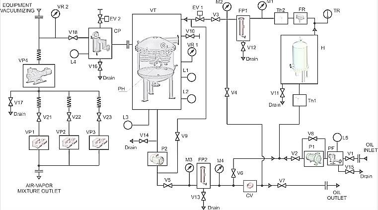
Figure 8 – Flow diagram
VT – vacuum column (tank); P1 – P2– oil pumps; V1– disk shutter; V2 – V7 – ball valves D 32; V8 – V9– ball valves D 20; V10 – V17, V19 – V20– ball valves D15; V18– vacuum valve; V21 – V23– ball valves D 32; Н – oil heater; CV– check valve; FP1, FP2 – fine filter; М1– М4 – pressure gauges; Th1– Th2– temperature controller sensor; TR – thermostat; FR – flow relay; VR1 – VR2– vacuum relay; L1 – L5– level sensors; VP1 – VP4 – vacuum pumps; PF– mesh filter; CP – coolant trap; EV1 – EV2 – electromagnetic valve
The Unit operates following modes:
- heating of transformer with hot oil (with filtration).
- oil degassing; (with filtration and heating)
- other equipment vacuumizing.
Ball valves V3andV4at cartridge filter FP1outlet allow to heat transformer with hot oil as well as to filter and circulate the oil. Ball valve V6 joins cartridge filter outlet FP2 to oil heater Нinlet for closed loop treatment of oil batch inside vacuum column VT and for Unit operation adjustment as well.
4. WARRANTY
Warranty period is 12 monthsfrom date of delivery.
The manufacturer guarantees normal and stable operation of the Unit if all installation, operation, maintenance, transportation and storage regulations, laid out in this manual, are observed.
If any manufacturing defects or failure of the Unit or it’s components through manufacturer’s fault are uncovered during warranty period, the user is entitled to make a claim to the manufacturer without disassembling the unit or it’s components. In the course of five days the user draws up a preliminary act and notifies the manufacturer of the defect.
Warranty is void in case of:
-
insufficient servicing and maintenance;
-
insufficient operation;
-
insufficient operation medias;
-
Unit design alteration;
-
use of defective tools;
-
use of non-original spare parts;
-
unauthorized alteration of the Unit or its components.
5. CONTACT DETAILS
Dielectric oil purifier manufacturer is GlobeCore.
Contact person:
Mr. Alexander Artiukh
(skype: globecore1)
Mr. Roman Gluschenko
(skype: romeo_globecore)
See phones numbers of nearest dealer at a contacts page