High vacuum transformer oil degassing Machine CMM-4A (capacity 4000 LPH)
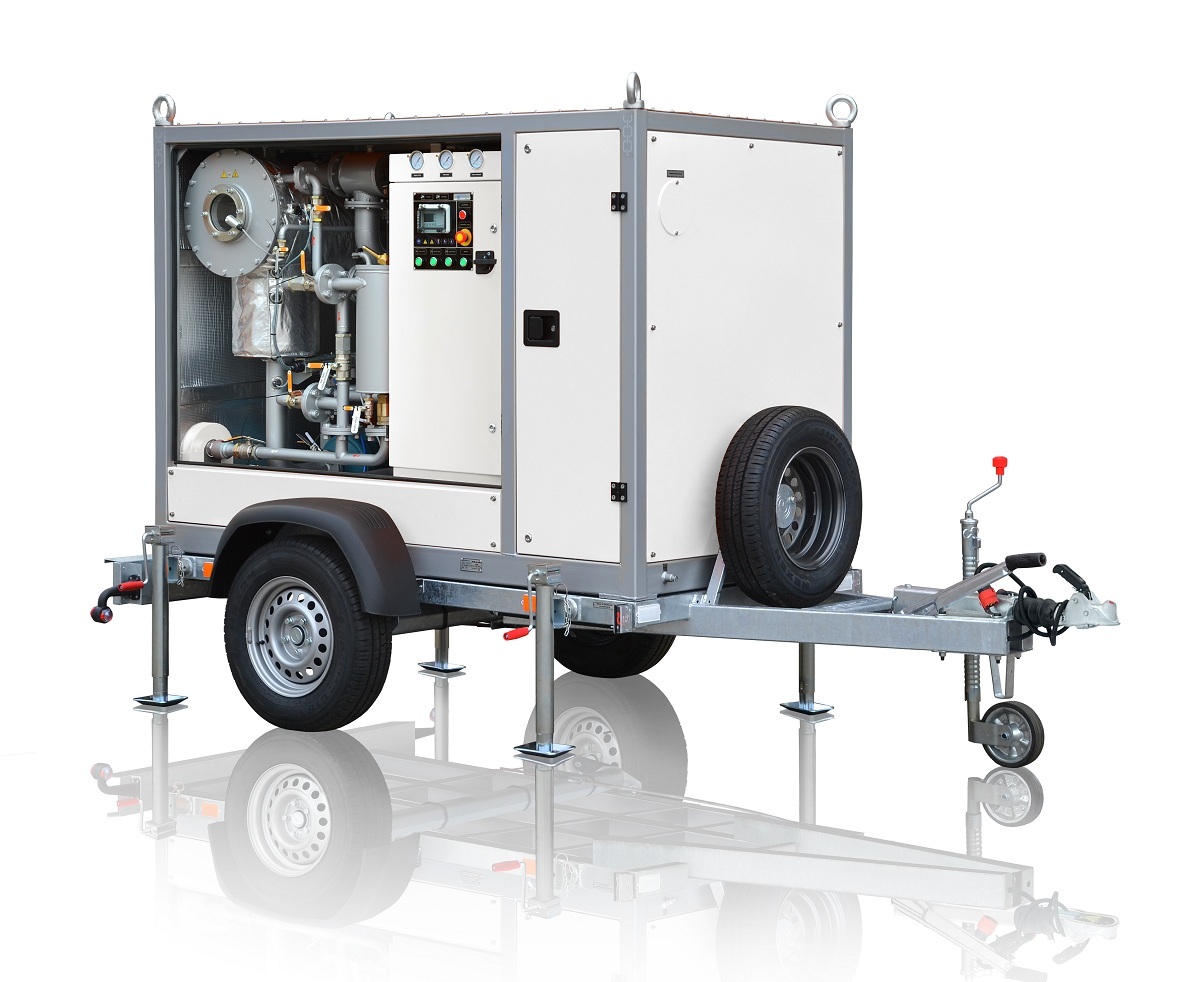
High vacuum transformer oil degassing machine CMM-4A (capacity 4000 LPH)
GENERAL INFORMATION
switches, etc.) up to 1150 kV of voltage.
|
The unit may be used for heating of oil-filled electrical equipment by
hot transformer oil, vacuum transformer drainage and transformer dry-out. Unit is used for installation, repair and maintenance companies which are dealing with transformer oil treatment. The unit is not fit for operation in explosive or toxic environment, as well as environment reactive to lubrication materials. |
|
| Performance in a single pass through the purifier at a full flow rate shall be as follows: Water Removal: From 100 ppm down to less than 10 ppm as measured by ASTM method D-1533. Gas Removal:From fully saturated with air (10 to 12% by volume) down to less than 0.25% by volume as measured by the ASTM Method D-2945 Particulate Matter Removal: 98% of particles over 2 μm Dielectric Strength: Improvement in dielectric strength up to 70 kV. |
TECHNICAL DATA
|
Parameter |
Value |
|
| 1. Capacity, m3/h, | ||
| – in degassing, dehydration and filtration mode |
0 – 4.0 |
|
| – in heating and filtration mode |
up to 7.0 |
|
| 2. Capacity adjustment range, m3/h |
0-4.0 |
|
| 3.PedroGil RVB 20.20 Roots vacuum pump capacity, m3/h |
280 |
|
| 4.* Processed oil parameters : | ||
| – maximum gas content, %, max. |
0.1 |
|
| – maximum moisture content, ppm, |
5 |
|
| – ISO 4406 industrial purity class |
9 |
|
| – mechanical impurities content, ppm, max | 8 | |
| – filtration rating, micron | 2…25 | |
| -breakdown voltage, kV, minimum | 70 | |
| 5. Maximum oil outlet temperature in heating mode , ºС |
85 |
|
| 6. Filtration coefficient |
>50 |
|
| 7. Outlet pressure, MPa |
0.35 |
|
| 8. Delivery head, m |
35 |
|
| 9. Oil heater power, kW |
54 |
|
| 10. Oil heater mean power, W/cm2, max |
1.1 |
|
| 11. Maximum power consumption, kW, max. |
69 |
|
| 12. Power supply parameters, 3 Phases + Neutral grounded |
|
|
| – voltage, V |
as required |
|
| – AC frequency, Hz |
50/60 |
|
| 3. Dimensions w/o trailer, max., mm |
|
|
| – length |
1520 | |
| – width |
1200 |
|
| – height |
1925 |
|
| 14. Weight, kg, max. |
1500 |
|
Note – * For inlet oil parameters as follows:
- gas content by volume less than 10,5%
- moisture content by weight less than 0,01% (100 ppm)
- temperature above 5 ºС.
TECHNICAL DESCRIPTION OF EQUIPMENT.
Configuration
The Unit (figure1.1) is an assembled container keeping all the
junctions, components and aggregates. Container is the one- or biaxial trailer
mounted. Front as well as back wall is lockable doors mounted for unobstructed
access and fanning. Unit is supplied mounted on two-axial trailer equipped by
torsional suspension axles, pneumatic wheels, coupling loop, support jacks,
pneumohydraulic braking system, parking brake hand lever and electrical
equipment.
|
There
|
|
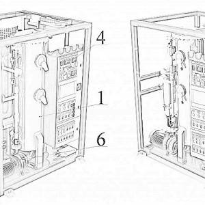 Figure 1.2.
transformer oil degassing machine general view
1 – vacuum column, 2 – oil heater, 3 – coarse
(25 micron) and fine (2 micron) filters, 4 – complete control unit, 5 – inlet pump, 6 – outlet pump, 7 – vacuum backing pump, 8 – booster (Roots) pump, 9 – receiver (oil trap), 10 – pipelines. |
|
Mesh filter is installed at the unit entrance and is designed for mechanical contaminants release. Filtration fineness is influenced by a 200 micron brass mesh mounted inside the case. It can be easily removed and cleaned.
Coarse and fine filters 3 purify the oil being processed. Filtration fineness is 25 and 2 micron. For filter general view see figure 2.
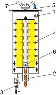 |
Figure 2. Cartridge filter of transformer oil degassing machine
1 – inlet oil pipe branch; |
The filter is lid and frame keeping one filtering cartridge inside. Filtering cartridges are made of EFMG filtering elements. To eliminate air within oil gain as well as to swallow it within oil drainage, filter uses air relieve plug. Body bottom is mounted with valve keeping branch pipe. Inlet and outlet oil branch pipes are body welded. The filtering elements (cartridges) are easy to replace and cleanable.
Oil heater 2 (figure 1.2) is a chamber keeping 2-sections heating cluster, inlet and outlet pipelines, as well as drainage valve. The heater represents a metallic column having the heating elements assembled inside it. Heater has a demountable structure to provide easy heating elements replacement. For oil heater overview watch figure 3.
| Figure 3. Oil heater 1 – vessel; 2 – oil heating block cover; 3 – heating elements; 4 – oil outlet pipe branch; 5 – oil inlet pipe branch; 6 – drain valve; 7 – oil temperature sensors (thermocouples); |
|
Use separate control switch buttons for each of two heating stages to manage overall cluster. Operate either each separate or all heating sections simultaneously (mode capacity results in operating section; thus, one stage is sufficient for degassing mode as long as heating and filtering mode supposes two-stage operating).
Employ temperature control sensor Th1 (Figure 6) to control oil temperature when heated.
Flow relay PП indicates operational fluid flow to prevent heating section failure and oil overheating. Heater is interlocked by a flow switch and is being energized only when oil is flowing through it. Heater is equipped with separate thermostat TS for extra-control and protection against overheating interlocked with heating elements.
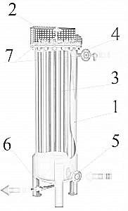
Vacuum column 1 is designed for degassing of transformer oil. For column overview watch figure 4.
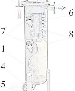 |
Figure 4. Vacuum column of of transformer oil degassing machine 1 – column; 2 – oil inlet pipe branch; 3 – vacuum system connecting pipe branch; 4 – oil outlet pipe branch; 5 – drain valve; 6 – activating filter (sprayer); 7 – sight glass; 8 – illumination. |
A shut-off valve is installed at the column for connection of vacuum system. Vacuum column includes also vacuum sensors VG1 and VG2, as well as level sensors L1 – L4.
Residual pressure of no more than 267 Pa is maintained in the column in the process of oil degassing. Oil is transported to the column by inlet pipe and through the collector to the activating filters (sprayers).
Owing to a special structure of the activating filter (sprayer) and high depression in column, gases and moisture are discharged intensively from oil.
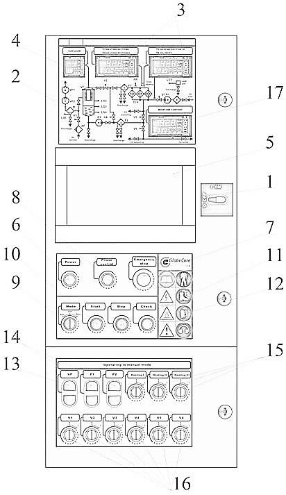
| Control cabinet is designed for placement of electrical components to facilitate Unit operation and equipped with electronic controller. It is a metal cabinet with lockable door. Electrical control and commutation circuits are panel located inside. Control buttons and light signalling devices are installed on the cabinet. For control cabinet general view watch figure 5.1 – Power supply manual breaker; 2 – Mimic diagram; 3 – Temperature measuring regulators; 4 – Vacuum measuring unit; 5 – Master controller; 6 – Power indicating lamp «Power» 7 – Emergency «STOP» button 8 – Indicating lamp of correct phase connection «Phase control» 9 – Mode select switch «Mode»; 10 – Turn on button (for operation in a set mode) «Start». 11 – Turn off button (for operation in a set mode) «Stop». 12 – LEDs operation control button «Check». 13 – Manual control switch for vacuum pump «VP1/VP2»; 14 – Manual control switch for oil pumps «P1», «P2»; 15– Manual control switch of heating elements «Heating I», «Heating I I», «Heating I I I»; 16 – Valve manual control switch «V1»…«V6». Figure 5. General view of control cabinet panel
|
 |
Control and measurement instruments
Column’s residual pressure is controlled by electronic vacuum controller RVE-4.1. Limit of effective measuring range is 0,133÷105 Pa. When operated oil heater is controlled by following measuring gauges:
- thermostat – for oil heater switch off if oil temperature is above 90º C set;
- flow relay – for oil heater switch off if no oil flow is supplied through oil heater;
- thermistor – for oil temperature measuring on heater outlet;
- manometers – to indicate contamination level of filter elements with regard to inlet and outletpressure in fine filters;
- level indicators – to control oil level in vacuum column.
The transformer oil degassing unit can be operated in the following modes:
- oil pumping;
- oil heating and filtration;
- oil dehydration and degassing;
- vacuumizing of external equipment.