Oil purification system CMM-1.2T (with Raschig rings, capacity 1200 LPH)
Oil purification system CMM-1.2T (with Raschig rings, capacity 1200 LPH)
GENERAL INFORMATION
Mobile Transformer Oil Purification Plant modelСММ-1.2T purifies insulating oils of mechanical particles and employs thermal vacuum treatment for water and gas removal. Operate the Unit when assembling, servicing and exploiting oil filled equipment (power transformers, high voltage switches, etc.) up to 1150 kV of voltage.
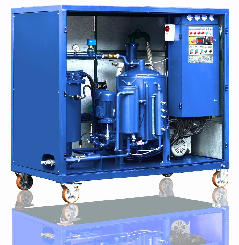
CMM-1.2 General view
Theunitmaybeusedforheating of oil-filledelectrical equipment by hot transformer oil, vacuum transformer drainage and transformer dry-out. Unit is used for installation, repair and maintenance companies which are dealing with transformer oil treatment.
The unit is not fit for operation in explosive or toxic environment, as well as environment reactive to lubrication materials.
When operating the unit indoors, gas exhaust line should be installed to evacuate gases into the atmosphere.
Performance through the purifier at a full flow rate
shall be as follows:
Water Removal: From 100 ppm down to less than 10 ppm as measured by ASTM method D-1533.
Gas Removal: From fully saturated with air (10 to 12% by volume) down to less than 0.25% by volume as measured by the ASTM Method D-2945
Particulate Matter Removal: 99.5% of particles over 1 μm
Dielectric Strength:Improvement in dielectric strength up to 65 kV.
| No | Parameter | Value | |
| 1 | Capacity, m3/h: | 1,2 | |
| 2 | Outlet oiltemperaturerange, ºС |
20-100 | |
| 3 | Processed oil parameters*- maximummoisturecontent by mass, ppm- maximum gas content, %- filtration finesse, μm- maximum mechanical impurities content, ppm- break down voltage, kV |
10,0 0,25 1 10 65 |
|
| 4 | Vacuum parameters | In vacuum pump, bar |
– 0,8 |
| In vacuum vessel, bar |
– 0,7 | ||
| 5 | Vacuum pump capacity, m3/h | 63 | |
| 6 | Maximum working pressure, bar | 6 | |
| 7 | Maximum delivery head , m | 40 | |
| 8 | Input pressure, bar |
1 | |
| 9 | Heating power, kW | 29 | |
| 10 | Oil heater mean power, W/cm2 |
1,1 | |
| 11 | Total power consumption, kW | 34 | |
| 12 | Voltage, 3 Phases + N, 50 Hz, V | 380 | |
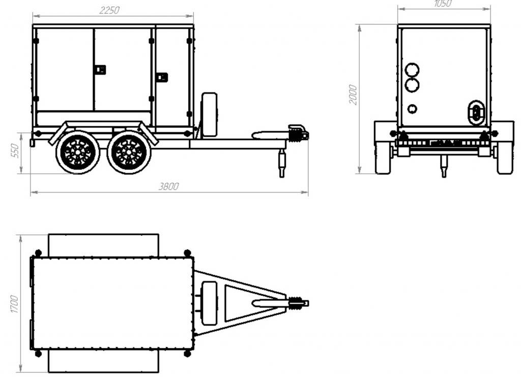
| 13 | Overall dimensions on trailer, mm:- length- width- height |
2250/3800 1050/1700 1450/2000 |
|
| 14 | Weight, kg | 1100 | |
Note – *For inlet oil parameters as follows:
- gas content by volume less 10,5%
- moisture content by weight less 0,01% (100 ppm)
- temperature above +20 ºС.
Scope of supply
| Item | Quantity |
| 1. Mobile transformer oil purification plant model CMM-1.2 (flow rate 1200 LPH) mounted on biaxial roadworthy trailer with metal weatherproof container |
1 |
| 2. Flow meter/totalizer BellFlow™ | 1 |
| 3. Photoelectric foam detector |
1 |
| 4. Hour counter | 1 |
| 5. Flexible stainless steel oil hoses with quick connectors, L=10m |
2 |
| 6. Set of spare parts for 2 years operation |
1 |
| 7. Operation and maintenance manual in English (written) |
1 |
| 8. Operation and maintenance manual in English (soft copy on CD) |
1 |
UNIT Technical description
Configuration
TheCMM-1.2 Unit (figure1.1) isanassembledcontainerwith lockable doors keepingallthe junctions, components and aggregates. Front as well as back wall is lockable doors mounted for unobstructed access and fanning. Unit is supplied mounted on a two-axial trailer equipped by torsional suspension axles, pneumatic wheels, coupling loop, support jacks, pneumohydraulic braking system, parking brake hand lever and electrical equipment. Unit is equipped with additional section for oil/vacuum hoses storage as well as for other instruments stock with lockable door.
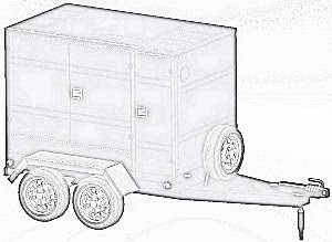
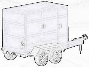
Figure 1.1 CMM-1.2 general view
There are the following components inside the frame: vacuum chamber, inlet oil pump, outlet oil pump, oil heater, coarse mesh filter, fine filter, control panel (complete control unit CCU), vacuumpump,pipeline system with shutoff and control valves. Toadjustparameters, Unitemploys digitaltemperaturecontrollers2ТRМ «Оven» (equippedwithТСМsensors), both pressure and vacuum gauges (М1-М2).
Vacuum pump cluster joins vacuum chamber and oil trap as well as vacuum pipeline which is shut-off valve equipped.
Mesh filter is installed at the unit inlet and is designed for mechanical contaminants release. Filtration fineness isinfluencedbya 200 micron brass mesh mounted inside the case. It can be easily removed and cleaned.
Inlet and outlet gear pumps supplytransformeroil into the Unit andsuck it outrespectively. The pumps are controlledfromthecontrolpanel and equipped with by-pass safety-valves to prevent system overpressure.
Coarse and fine filterspurify the oil being processed. Filtrationfinenessis5 and 1 micron. For filter general view see figure 2.
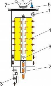
Figure 2. Cartridge filter
1 – inlet oil pipe branch; 2 – treated oil outlet pipe branch; 3 – sludge drain valve; 4 – filtering
cartridge; 5 – air release valve; 6 – magnets; 7 – clamping lever
Thefilterislidandframekeepingonefiltering cartridge inside. Filtering cartridges are made of EFMG filtering elements. To eliminate air within oil gain as well as to swallow it within oil drainage, filter uses air relieve plug. Bodybottomismountedwithvalve keeping branch pipe. Inlet and outlet oil branch pipes are body welded.
The filtering elements (cartridges) are easy to replace and cleanable.
Oil heater is a chamber keeping heating coils, inlet and outlet pipelines, as well as drainage valve. Foroilheateroverviewwatchfigure3.
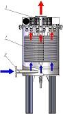
Figure 3. Oil heater
1 – oil heating block; 2 – cold inlet oil pipe branch; 3 – heated outlet oil pipe branch
Employtemperature control sensor TP (Figure 6) tocontroloiltemperature when heated.
Flow relay PП indicates operational fluid flow to prevent heating section failure and oil overheating. Heateris interlocked by a flow switch and is being energized only when oil is flowing through it. Heaterisequippedwith separate thermostat forextra-control and protection against overheating interlocked with heating elements and sound and visual alarm in case of overheating.
Vacuum column is designed for thermal vacuum dehydration of transformer oil. Forcolumn overview watch figure 4.
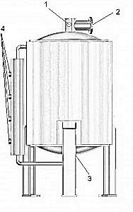
Figure 4. Vacuum column
1 – inlet pipe branch;2 – vacuumsystemconnectingpipe branch;3 – treated oil outlet pipe branch;4 – level sensors with visual level indicator;
A shut-off valve is installed at the column for connection of vacuum system. Vacuum column includes also level sensors L1 – L4, as well as tubular visual level indicator.
Oil is transported to the column by inlet pipe and through the injection sprayer (oil disperser) to the Raschig rings.
Sprayer design as well as usage of special shaped Raschig rings allows for oil intensively exhaling gases and moisture.
The unit is equipped with the photo electric foam detection system preventing any treated oil access into the vacuum system.
Control cabinet is designed for placement of electrical components to facilitate Unit operation. Itisametalcabinetwithlockabledoor. Electricalcontrolandcommutationcircuitsarepanel locatedinside.
Control buttons and light signaling devices are installed on the cabinet.
Control cabinet is also equipped with the hour meter, as well as cabinet automatic ventilation system. For control cabinetgeneralviewwatchfigure5.
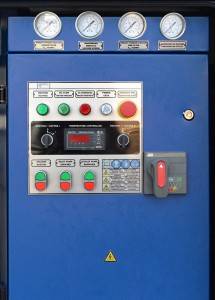
Figure
5. General view of control cabinet panel
Control and measurement instruments.
Column’s residualpressureiscontrolled byvacuum meters.
When operated the unitiscontrolled byfollowing measuring gauges, instruments and
devices:
- thermostat- for oil heater switch off if oil temperature is above preset temperature (maximum recommended is 90 0C to prevent oil overheating and degradation);
- flowrelay- for oilheaterswitch offif no oil flow is supplied through oil heater;
- thermistor – foroil temperature measuring inside the heater;
- manometers – to indicate contamination level of filter elements with regard to inlet and outlet pressure in fine filters;
- vacuum meters – to control the necessary vacuum range in the vacuum chamber;
- level indicators – to control oil level in vacuum column;
- foam detection system – to prevent extremely foam formation and treated oil access into the vacuum system
- flow meter/totalizer – for measurement of current/total quantity of treated oil.
Principle of operation
The CMM-1.2 flow diagram is shown below. Please note this diagram shows a simplified version of unit operation and serves only a basic sketch. The final scheme may vary depending on customer’s specification.
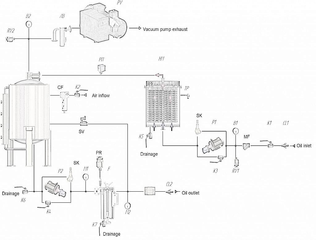
Flow diagram:
CV – vacuum chamber;HM – oil heater; PV – vacuum pump; P1 – inlet gear pump; P2 – outlet gear pump; К1 – inputvalveDN25; К2 – air inflow valve DN15;М1, М2 – manometers; К3 – К8 – valves DN15; SV– solenoidvalve; КО– non-return valve;MF– strainer mesh filter; F – fine filter cartridge; SK – safety valve; В1 – В2 – vacuummeters; PR – pressure relay; TP – temperature sensor; RV1, RV2 – vacuum relay;CL1, CL2 – camlock type inlet and outlet connectors; CF– coalesce inlet air filter; ЛВ– oil trap; РП – flow relay
Overall dimensions on trailer
WARRANTY
The manufacturer guarantees normal and stable operation of the Unit if all installation,
operation, maintenance, transportation and storage regulations, laid out in this manual, are observed.
Warranty period is 12 months from the date of supply.
If any manufacturing defects or failure of the Unit or it’s components through manufacturer’s fault are uncovered during warranty period, the user is entitled to make a claim to the manufacturer without disassembling the unit or it’s components. In the course of five days the user draws up a preliminary act and notifies the manufacturer of the defect.
Warranty is void in case of:
- insufficient servicing and maintenance;
- insufficient operation;
- insufficientoperationmedias;
- Unit design alteration;
- useofdefectivetools;
- use of non-original spare parts;
- unauthorized alteration of the Unit or its components.