Category Archives: Solutions

Oil Pump Functions And Configuration

Oil pumps are used where it is necessary to keep constant circulation of oil: lubricating and pumping systems etc.  Hence the purpose of these devices is circulation and pressure injection.

Depending on the operating principle there are two types of oil pumps: gear and rotor. Gear pumps can have external gearing or internal gearing.

The main purpose of gear pumps is creating constant pressure while rotary pumps are aimed at changing oil supply depending on the technological equipment operating modes.

Pumps with external gearing consist of a housing and two gears (driving gear and idler gear).  On one side of the pump there is a vacuum chamber in which oil suction occurs. Next, the oil gets between gear teeth and the housing, and then it is fed into a discharge chamber and oil filter.  For the pump to be operated with maximum efficiency, the gaps between the gear teeth and between the gears and the housing should be minimal.

Pumps with internal gearing consist of a housing and two internal gears.  The structural feature of such construction is that one gear is placed inside the other one and their axes do not coincide.  Also, idle gear diameter is usually less than that of the driving gear.  Due to the difference in diameter, crescent-shaped space is formed between the gears.  A separation sector which injects the oil is placed inside that space.  First, the oil passes through a vacuum chamber and then gets between the teeth of the gears and the separation sector.  Next, the oil is transferred to the pumping chamber.

Rotary oil pumps operate on the same principle as internal gearing pumps.  The main difference lies in the fact that two rotors consist of a small number of blades.  Their location is eccentric.  The principle of rotary pumps operation is as follows. Rotation of inner rotor blades leads to the formation of moving cavities of variable volume between the blades and outer rotor pits.  If such cavity passes over a vacuum chamber, its expansion occurs with subsequent absorption of oil.  Then, the cavity volume is reduced, which leads to the compression of oil.  During the passage over a discharge chamber oil is fed into the system under the required pressure.

Anti-Corrosion Tank Protection

Corrosion is a negative process, which is basically a destruction of metal surfaces at the influence of environment.

Ground-based metal tanks are subjected to atmospheric (external surfaces), air-vapor (roof inner surfaces and tank top rings) and soil (external surface of the tank bottom) corrosion.

Atmospheric corrosion is a result of electrochemical processes. Thin film of moisture or its separate droplets appearing at the tank surfaces in humid atmosphere act as electrolytes. In order to protect external surfaces of tanks from corrosion it is advisable to paint them with special weather-resistant paint coatings.

Corrosion of inner surface of the roof occurs with presence of sulfur compounds in gas phase, or when moist air gets into a tank during the process of ventilation. The moisture, that penetrated the inside of the tank, condenses, and the presence of oxygen and hydrogen sulfide create all prerequisites for galvanic corrosion.

Corrosion of inner surfaces of the walls occurs as a result of chemical interaction of metal with sulphurous oil-products.

Tank apron  and bottom ring are subjected to corrosion more than any other parts, caused by their contact with water settled at the top and bottom. These types of water usually contain aggressive acids, gases and salts; which provokes intense corrosion of metal that comes in contact with these substances.

The following measures can be applied to protect internal surfaces that contact with gaseous phase:

  • aluminum spraying;
  • treatment by cement-based coating followed by surface coating with magnesium-fluoride-silicon solution;
  • coating with chemically stable insoluble polymerizing substances.

Tank bottom protection is achieved by:

  • adding alkalis or corrosion inhibitors into bottom settled water in order to neutralize acids;
  • asphalt coating or coal and sand coating below the layer of water at the  bottom;
  • cement grout coating;
  • metallized coating;
  • ground protection.

Soil corrosion is a process of metal destruction which occurs as a result of metal and electrolyte interaction. Intensity of such corrosion depends on soil composition as well as its humidity and aeration.

Dry sand has minimal corrosive effect on metal tanks, so it is recommended to use sand as the base to install tanks on.

How to protect ground-based tanks? Bituminous insulation is most commonly used to protect ground-based tanks. But it should be noted that it is not sufficient. Bitumen coating may lose its insulating properties with time and soil electrolytes may penetrate into metal surface of  tank bottom.

Therefore it is recommended to protect tanks bottoms using electrochemical methods (galvanic anodes, cathodic protection) in addition to bituminous insulation.

Cathodic protection from soil corrosion is a fairly effective and cheap method. Its aim is to artificially turn the tank surface, which contacts with soil, into a cathode by connecting it with a DC source circuit.

Cathodic protection is creation of an electrical circuit in which tank bottom acts as cathode, and protectors act as anode. Protectors are metal rods with a higher negative potential and electrochemical equivalent. Therefore, protectors corrode first, and not tank bottom.

Cathode protection is worth using where tanks service life is 10 years and more.

Protection of inner surfaces of the walls

Purity of stored oil-product protects tank walls from corrosion.  GlobeCore UVR oil purifiers regenerates and purifies oil. It cleans dark diesel and heating oil, makes it lighter colored, removes sulfur and hydrosulfuric compounds as well as removes gum, dirt and gas condensate.  The final oil-product fully conforms to normative cleanliness level after purification. It is freed from unpleasant odour and does not darken and oxidize for a long time.

The great advantage of UVR oil recycling plants over other similar equipment is their versatility  i.e. ability to work with practically all types of oil-products such as transformer, turbine and industrial oils, diesel and heating oil, gasoline, kerosene.

GlobeCore equipment removes unwanted components that cause corrosion. Thus UVR oil purifier not only improves purity of processed oil, but also protects oil storage tanks.

Follow the link to see the specifications of this equipment. Use one of our contacts to make an order.

Transformer Oil Processing Plant

Transformer oil in most cases contains solid particles (metal oxides, cellulose fibers, etc.), water and dissolved gases. These impurities need to be removed.

In practice special centrifuges with capacity of 10,000 L/h are used to remove emulsified moisture and bulk solids. The processed oil can be used for 35 kV  voltage transformers.

Vacuum degassing plants removes dissolved moisture, gases and light impurities. Also quite effective is oil drying with Na and Ca zeolite achieving the residual moisture content of 0.5%. This technology lowers the moisture content in oil to 10-15 g/t.

Mechanical impurities are removed by filtration. The final effectiveness of such purification is determined mainly by the size of filter material’s porous barriers.

Magnetic filter is known as another tool to remove powdered metals particles from transformer oils.

These purification methods cannot be used separately.  As in practice there are no oils contaminated by cellulose particles only, or by metal particles only or containing water or gases only. Therefore a few techniques are used to achieve the desired efficiency. Although their combined purification meets the requirements they are too time-consuming, power- consuming and complicated.

This calls for a better design of transformer oil recycling plants.

GlobeCore mobile stations are designed to reach the level that meets the highest quality requirements. It is possible to use your own transformer oil processing plant directly on your premises, making it handier and cheaper. It saves expenses on shipping and treatment of transformer oil at specialized facilities.

Plant for Transformer Oil Regeneration is a New Life of Transformers

The problem of old equipment is constantly faced by the management of power plants. According to studies the number of power transformers, that were used for more than 25 years consists of 40%. Experts agree that most susceptible to damage are internal isolation of transformers and voltage regulators and bearings.

Replacement of all old equipment is not possible, not only because of overall economic situation. But also with views on cost recovery. In our commercial world of quick profits, replacing powerful equipment would pay off in quite a long period of time. On the other hand, the service life of most transformers is not yet completed and it can be extend, with constant control and maintenance. Nevertheless, allocating huge funds for repair – is inappropriate waste when there are other solutions to this problem.

CMM-R (transformer oil reclamation plant, oil purifier) by GlobeCore, has been operating on the international market for many years. It was developed specifically to resolve this issue. Its method of recovery of dielectric strength and chemical composition of insulating oils is one of the most profitable methods of oil recovery.

CMM-R installation has a number of advantages. Firstly, with its help it is possible to regenerate insulating oil inside transformer itself (online offline). Secondly, the sorbent used for purification is “Fuller’s Earth”, which has an ability to repeatedly restore its characteristics, continuously treating oil without replacement for 300 reactivations for 1.5 – 2 years.

During oil recycling process the oil in transformer dissolves the deposits on winding insulation and the sorbent, in turn, withdraws it. Acid and decomposition products are removed from oil, following by clarification. The oil reclamation process also increases oxidation stability of oil and diminishes its ability to dissolve gases, extending operating life of recovered transformer oil.

As mentioned earlier, the essence of regeneration process is in passing oil through sorbent with micro-porous structure, participating in “molecular filtration.” Oil decomposition products and unwanted impurities remain in the pellets of sorbent. After that CMM-R installation reactivates the sorbent, i.e. it purifies it directly.

In addition, the installation is equipped with new modern equipment, showing high level of efficiency. Experts have positive comments about excellent results of transformer oil processing, confirming that the condition of recovered oil conforms to fresh transformer oils.

CMM-R installation by GlobeCore – is a system for complex processing of oil. The design of the installation is mobile with gives a possibility of operating it directly next to transformer. Installation is not a static unit, and can be transported from one transformer to another.

Equipment various technological parameters is controlled and managed by an external touch screen control panel. Programmed initially, it does not require operator supervision.

Every enterprise is facing the problem of saving resources and constantly keeping abreast with modern technology market. Using power equipment has never been so easy as with GlobeCore.

Drying and Cleaning of Transformer Oil

Even the cleanest transformer oil coming from the manufacturer requires drying and degassing, as it is not possible to completely prevent the ingress of water and air.  Also transformer oil can be contaminated with foreign particles during transportation.  There are cases of incomplete removal of pieces of sorbents at the final stage of oil production.

In case of insufficient rinsing of transformer tanks, colloidal inclusions may get into the oil.  They drastically deteriorate its insulating properties and reduce its flash point.  The necessary methods of processing oil include: drying, degassing, filtering, and in some cases, adsorption filtration.

Transformer oil drying:

  • thermal vacuum diffuse drying and degassing in special installations;
  • filtration through a dried paper filter, with simultaneous drying and removal of solid particles.  The disadvantage of this method is the need of paper drying.  To achieve the transformer oil moisture content of 10g/t, cellulose product moisture content should not exceed 2-3%.  There is also the danger of paper degradation under the influence of moisture and subsequent oil pollution;
  • adsorption drying with zeolites.  This method dries up to 1000 tons of transformer oil without zeolite regeneration.  If we compare the price of zeolite and vacuum degassing plants, it should be noted that the first ones are much cheaper.  They can be used where oil does not require degassing.

Operation process of vacuum oil degassing unit consists of two stages.  The first stage is oil foaming under the influence of vacuum, which stimulates an intensive diffusion of gases and water vapor.  However, a small portion of these substances still remains after deposition of foam.  During the second stage, vacuum provokes slow diffusion of gases from a thin layer of oil in the unit.  The main difference of the second stage is higher vacuum and heating of oil. The overall efficiency of the process is due to variation of temperature and flow of oil, supplied to the oil purifier unit.

Removal of mechanical impurities.  Achieving a required purity of  operated transformer oil is no less important than its profound dehydration.  There can be the following sources of foreign particles:

  • production (cellulose fibers, dust, microparticles of iron and copper);
  • installation (sand, dust and dirt particles from the atmosphere, particles of sorbent).

The main task of transformer oil reclamation and purification is  to remove solids with particle size less than 25 microns.  It is necessary to maintain both at refill (in this case, oil is forced through imperfect filters) and during the purification directly in the transformer tank.  In the latter case, small impurities move in the oil at relatively low speed.  As a result, they are distributed by convection currents and simply fail to enter the filter.

Transformer oil breakdown voltage and coefficient of variation is measured to assess the presence of large mechanical particles or their amount.  But this criterion can rather be considered indirectly.

For more information, the analysis of dispersion particles is conducted.

Fuller’s Earth (Fuller Earth): Features and Application

Fuller's earth

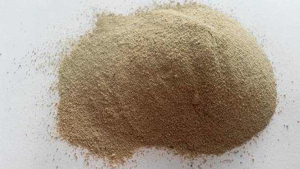
Fuller’s earth is a natural material of grayish-white, brown, green, blue or olive color, consisting approximately 70% of silica. Its structure also includes: sapphire crystal, magnesium oxide, iron oxide and calcium oxide. Its present name Fuller’s earth received a few centuries ago, when masters of wool cleaning (“fullers”) began to use bleaching clay to remove oil stains.

This effect was achieved due to high adsorption properties of the material. Further Fuller’s earth was used for bleaching and processing of vegetable oils and fats. At present, there are numerous practical applications of this material, among which it is worth noting:

  • manufacture of insecticides and fungicides;
  • stain removal of oil spill;
  • visualization     of explosions effects in films with military themes;
  • cosmetic masks;
  • manufacture of catalysts for petroleum and chemical industries;
  • manufacture of pharmaceuticals, etc.

Now most volumes of Fuller’s earth are used in bleaching and cleaning petroleum products, as well as secondary processing of edible oils. The richest deposits of it are located in the United States (Georgia and Florida), India, England and Germany.

GlobeCore is one of the leading manufacturers and suppliers of equipment for cleaning and regeneration of transformer oils. Adsorption qualities of Fuller’s earth did not go unnoticed by our design department and were used successfully in CMM-R units for processing electrical, industrial and turbine oils.

CMM-R consist of degassing, regeneration and inhibition blocks. Fuller’s earth filter is used in the second block. The innovation introduced successfully by GlobeCore, was to reactivate sorbent (Fuller’s earth) directly during oil cleaning. It allows, firstly, to solve the problem of disposal of bleaching clay, and, secondly, to reduce the duration of the treatment process. Furthermore, restoration of Fuller’s earth saves the portion of oil which previously could not be removed from the sorbent during its recycling.

CMM-R regenerates used oil and obtains oil product suitable for further use. Treatment of oil is carried out directly in transformer tank in working mode, which is especially important when the transformer could not be off-line.

Transformer Oil Treatment to Improve Reliability of Transformers

High cleanliness class of oil used in operation is a basic requirement for modern hydraulic and lubrication systems.  Though manufacturers of oil-products do not always provide a proper level of cleanliness, forcing consumers to carry out additional treatment of oil before it can be used.

In energy industry transformer oil is an important element. It performs the functions (insulation, heat removing), which are indispensable for normal operation of basic equipment (transformers).

During operation, oil is subjected to contamination with impurities of various composition and size.  This is caused by normal wear and tear of moving parts of the equipment, oxidation of the insulating liquid and chemical reactions inside the transformer.  As a result, moisture is accumulated in oil, causing destruction of windings insulation, aging of insulating fluid, precipitation of additives in the form of sludge. Contained contaminants in such oil are: aging products, water, corrosion products, silicates, gases, acids, oxidation products, winding insulation paper fiber etc.  It is obvious that the presence of these impurities has a negative impact on transformer working conditions due to the defective performance of oil. In worst-case scenario, it does not only slow down  production, but cause  failures.

About 95%, of contaminants are  particles smaller than 5 microns and they are the most dangerous ones.  The main difficulty is the fact that such impurities are polar, therefore they can gravitate and adhere to the inner walls of transformers.  Such adhesion prevents the exit of water accumulated inside paper insulation of the windings, thus speeding up the process of its destruction.  Also contaminants worsen heat transfer between oil and the windings, which leads to increased operating temperature of the transformer and a decrease of load. The negative impact of pollutants leads to oil treatment and recovery.

The main ways to maintain operational properties of transformer oil are

  1. continuous regeneration with adsorbents using adsorptive and thermosiphon filters;
  2. hermetically sealed equipment;
  3. dehumidifying filters;
  4. film or nitrogen protection;
  5. necessary concentration of anti-oxidizing additives;
  6. cooling of oil.

The leading role among the above mentioned measures is given to regeneration, since it allows to work with oil which already has degraded performance characteristics.  GlobeCore design department developed a unique technology of transformer oil treatment and filtering using Fuler’s earth sorbent (CMM-R plants).  It restores transformer oil operational indicators to a level sufficient for further use.

The results of transformer oil testing before and after treatment

Parameter

Before regeneration

After regeneration

Norm according to IEC 60296

1 Appearance

Cloudy, dark brown

Clear, uncolored

Clean, free of sediment and suspended solids

2 Acid number, mg KOH per 1 g of oil, not more than

0.63

0.01

0.01

3 Corrosive sulfur

Presence

Absence

Absence

4 Moisture content, ppm, not more than

170

5

30-40

5 Breakdown voltage, kV, more than

11

73

30-70

6 Dielectric loss tangent at 90 °C, %, not more than

4.0

0.001

0.005

7 Gas content, %

12

0.1

8 Surface tension at 25 °C, mN/m

22

45

40

9 Mechanical impurities, micron

50

0.2

Absence

10 Anti-oxidation stability test

– acid number, mg KOH per 1 g of oil, not more than

0.2

1.2

Note:

*  depending on the type of oil.  See more about transformer oil testing methods

Transformer oil reclamation technology using Fuller’s earth sorbent

GlobeCore technology of continuous regeneration of dielectric fluids improves the quality of transformer oil performance and extend its service life.

Waste Oil Reclamation Technologies

The article analyses existing approaches to transformer oil reclamation. It considers acid and alkaline cleaning, vacuum distillation, rectification.  It specifies the advantages and disadvantages of each method.

In recent decades, mankind has been facing  a threat of ecological catastrophe, This forces to revise  procedures dealing with industrial waste, especially waste oil, an attitude of which also changed.  A recommended measure for waste oil is – reclamation – restoration of its operation properties  and reuse for its intended purpose.

Different methods are used for oil reclamation. When choosing a restoration technology, it is important to consider waste oil characteristics.  In some cases only physical method is enough  to achieve a good result. In other cases a sequence of processes is needed.

Oil collection and   reclamation should be carried out separately, or in groups.  The final product is not constant and is defined by the depth of purification and the selected reclamation technology.

Oil reclamation is removal of contaminants or separation of undesirable components: usually including emulsified water, light combustible products, and other mechanical admixtures.  Valuable hydrocarbon makes up at least 70-80 % of waste feedstock, low-boiling fractions make up 10.5 % and resinous substances  10-20 %.

Some purification processes are based on the interaction of undesirable components with chemical reagents.  These processes include acid cleaning,  especially in industrial practice.

Acid cleaning is mainly used to remove:

  • asphalt-resinous substances;
  • oxidized products;
  • unsaturated hydrocarbons;
  • compounds containing sulfur and nitrogen;
  • aromatic compounds.

In most cases, 92-96 % sulfuric acid is used for purification.  Its consumption is different for each case, and should be determined experimentally.  Optimal flow temperature is also found by tests and in most cases is 35-80 °C.

Result of this purification is acid sludge  Its disposal requires additional high costs.  This is one of the main drawbacks of this method.

Alkali cleaning can be used as an autonomous process, or in combination with sulfuric acid cleaning.  It removes the following substances:

  • organic acids;
  • sulfur-containing compounds;
  • phenols.

In most cases, 2-15 % water solutions of sodium hydroxide are used.  Its required amount is also determined experimentally and ranges from 2 to 15 %.  The degree of purification depends on the flow temperature, so the neutralization is carried out at 70-90 °C.

Alkali contacts with oil for 5-10 min.  It is necessary to stir it during the process.

Wastes resulting from alkali cleaning, may be used in the production of naphthenic soap and emulsifiers.

Fractional distillation and rectification under vacuum are also known as purification methods.  Distillation is separation of hydrocarbons of various molecular weight.  Vacuum distillation and rectification are splitting waste oil into fractions of different viscosity.

When choosing a particular type of waste oil reclamation, it is necessary to consider the results of preliminary studies, that allow to calculate the approximate quality of the product.

Fluids Filtration Systems in Mining Machines

Mining machinery is very expensive equipment.  Its operation requires specific technical knowledge.  Its effectiveness directly depends on maintenance, service and qualification of personnel.  However the principal role is the quality of filtration of  working fluid, which is subject to contamination due to intensive use.

An appropriate level of purity of  working fluid:

  • increase service life of drive units and improve machine availability;
  • increase drive efficiency, thus raising equipment productivity;
  • reduce fuel consumption (by 7-10%) and hydraulic oil consumption (by 15-25%).

Each mining machine, coming out of production, has a standard level of oil purity.   In theory, this purity level of  working fluid  should stay throughout the service life of mining equipment.  In practice, actual contamination of hydraulic oil significantly exceeds the norm, and regular filters are not coping with it.  Under such conditions, the main hydraulic equipment of, let’s say, excavators are able to work only 30-70% of their nominal life.

Thus, the main reason for reducing mining machinery operation is in unsatisfactory condition of their working fluids.  In order to prevent accidents and forced outages – working fluids should be controlled using special equipment for sampling and analysis.

The main task of monitoring working fluids – is identifying the load on  filters and oil pre-treatment, as well as oil regeneration and reuse.  In many cases, regular sampling shows the stability of the chemical composition of oil in operation. The quality of oil is also monitored on a seasonal basis.

When  contamination control results exceed the set values oil and fuel pre-treatment is carried out  When oil and fuels are supplied having 14 to 16 cleanliness class.  Practically, this means that 18 to 75 grams of contamination must be removed from each filling container before oil fill.

It is suitable to be reused after a deep oil filtration (removal of finely dispersed water and particles with a size of less than 3 microns).

Filtration of mining machinery working fluids to reach the required cleanliness class can be achieved by:

  • improved  existing filtration systems;
  • additional filtering systems;
  • special devices, reducing fluid contamination during transportation and fills;
  • regeneration plants.

Of course, the best effect is achieved by using a variety of measures.  But  it is necessary to make economic calculations, since the introduction of any new measure aimed at maintaining the operating condition of oil entails certain financial expenses.

But the benefit of regeneration systems is beyond doubt.  By purchasing mobile oil filtration plants, you kill two birds with one stone.  First, you get an opportunity to use waste materials again for their intended purpose.  Regenerated oil is comparable to new oil in terms of quality and performance characteristics.  It eliminates the need for purchasing fresh oil for replacement.  It saves expenses.  Secondly, environmental aspect is very important.  Multiple recoveries of working fluid properties postpone the problem of disposal for a long time.

GlobeCore manufactures equipment that  solves absolutely any problem in the field of mining equipment operating fluids filtration.  It is possible to perform oil pre-processing before filling in the system, and regeneration of used oil.  GlobeCore processes restore purity class of working fluids to quality values.

With GlobeCore mining machinery live long and preserve  the environment!

Classification of Transformer Oil Purification Filters

All the transformer oil  filters can be divided into surface filters and depth filters.

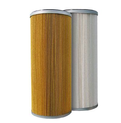
The structure of a surface filter includes a thin-layer filter membrane, where contaminants are retained on the surface of filter elements.  This type of filters use a variety of fabrics, nets, paper, and materials capable of forming gaps. They retain impurities the size  of which exceed the size of the filter material pores or gaps.

The structure of depth filters includes a thick-walled filter membrane (25 mm).  The surface of fluid inlet is small.  The contaminants can be retained not only on the surface but also in the depth of the filter.  Thick cardboard, mineral wool, felt, wood flour, cellulose pulp, cotton yarn, plastic, cermet, and other materials are used for depth filters.

The advantage of depth filters is the ability to hold contaminating particles of different sizes.  This is achieved due to the presence of a plurality of pore channels in a filtering membrane with different pore sizes and sections.  The disadvantage of such devices include the highly developed internal surface of the porous structure, which leads to a high adsorption activity – making cleaning oils containing additives not possible.  Each depth filter made of a certain material has its own disadvantages.  Therefore, when choosing a transformer oil purifier it is advisable to analyze the properties of its filter material.

Depending on the multiplicity of use filters can be changeable, and irremovable. Irremovable filters do not require replacement of the  filter element – it is  restored by : cleaning, washing, calcination, etc. That is their main advantage.  Generally these filters are made of more expensive materials and not always completely restore their properties.

Changeable filters have a limited period of use, after completion of which they are replaced with new ones.

Depending on the subtlety of filtration (the minimum size of retained contaminant particles) all purifiers are divided into coarse filters and fine filters.

Coarse filters remove the largest  impurity particles from oil, thereby facilitating the task of fine filters.

The task of the latter is cleaning oil from all hazardous particles of pollution.

IMG_1_2_33